English (GB)
20
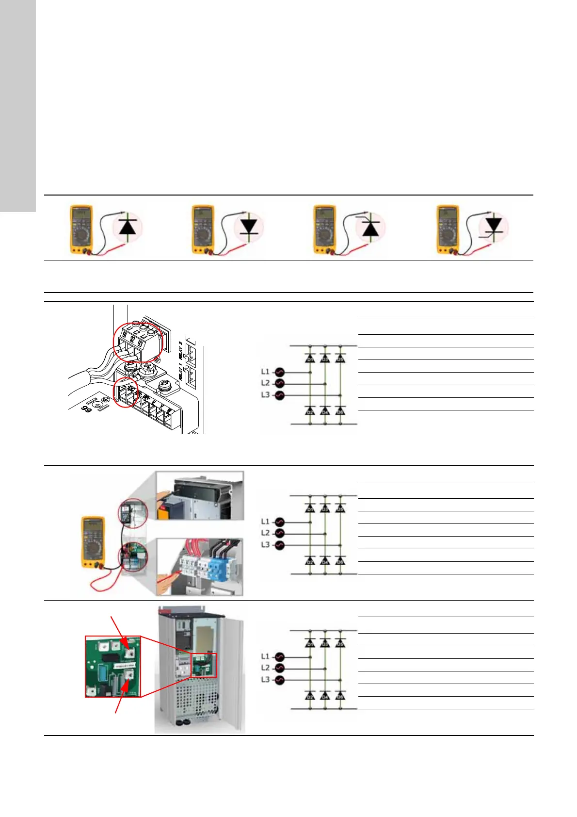
4.1 Checking the rectifier, static test
Always carry out the static test of the rectifier after each repair.
Before beginning the test:
1. Switch off the mains supply.
2. Remove the supply cable.
3. Set the multimeter to diode test.
The position of the terminals DC+ and DC- differs from enclosure
to enclosure.
Measurement on diodes and thyristors
Note that the diodes are not fitted directly on the terminals where
the measurement takes place. OL (Open Line, i.e. no connection)
may therefore indicate an interruption between the terminal and
diode. Check this before replacing the diode or the board where
the diode is fitted.
Diode drop voltage approx. 0.4
V; < 0.3 V or > 0.5 V: Diode
defective.
OL: Diode blocked = OK.
Other indication: Diode
defective.
OL: Thyristor blocked = OK.
Other indication: Diode
defective.
OL: Thyristor blocked = OK.
Other indication: Diode
defective.
Enclosures A2, A3, A5, B3
TM03 9014 2807
Measurements
Step 1 Step 2 Step 3 Step 4
+DC - +
-DC + -
L1 + - - +
L2 + - - +
L3 + - - +
Indication 0.4 OL 0.4 OL
+ = positive test pin
- = negative test pin
Terminals in enclosures A2 and A3 (shown with
mains supply cable connected).
Enclosures A5 and B3 have similar terminals.
Enclosures B1, B2
Measurements
Step 1 Step 2 Step 3 Step 4
DC+ - +
DC- + -
L1 + - - +
L2 + - - +
L3 + - - +
Indication 0.4 OL 0.4 OL
+ = positive test pin
- = negative test pin
Enclosure B4
Measurements
Step 1 Step 2 Step 3 Step 4
DC+ - +
DC- + -
L1 + - - +
L2 + - - +
L3 + - - +
Indication 0.4 OL 0.4 OL
+ = positive test pin
- = negative test pin
 Loading...


