English (GB)
19
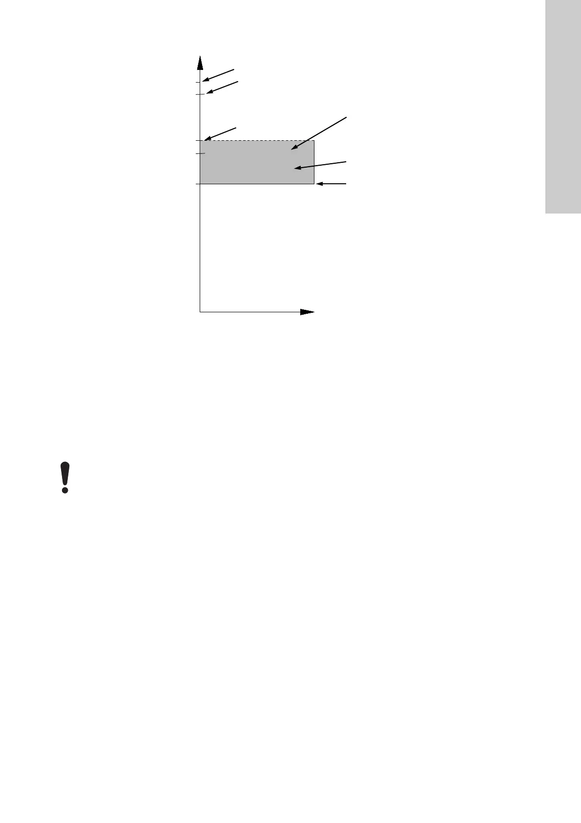
Overload alarms
Fig. 7 Overload alarms
4. Checking the mains components
The check of the mains components of CUE is divided into these
single
procedures:
4.1 Checking the rectifier, static test
4.2 Checking the IGBTs, static test
4.3 Checking the IGBTs, dynamic test
4.4 Checking the intermediate voltage
4.5 Checking the current sensor
4.6 Setting the type code.
TM04 1969 1508
I
motor
I
CUE, 1 minute
- 110 %
I
short
I
CUE
- 200 %
I
CUE, max.
- 100 %
I
motor
<= I
CUE, max.
(nameplate)
48/1
0 Overload, thermal
55/12 Overload, torque
55/59 Overload, current
The pump is overloaded, but the alarm is
not active yet.
48/9
49/13
48/16
If it is necessary to replace rectifiers and/or IGBTs, it
is important to clean the heat sink of old cooling
paste and apply an even layer of new cooling paste
over the entire heat sink. Some CUE enclosures
have rectifiers and IGBTs on the power board.
 Loading...


