English (GB)
21
4.2 Checking the IGBTs, static test
Always carry out the static test of the IGBTs after each repair.
Before beginning the test:
1. Switch off the mains supply, and wait until the capacitors have
discharged.
2. Remove the supply cable.
3. Remove the motor cable.
4. Set the multimeter to diode test.
The test shown here is actually a test of the freewheel diode of
the IGBT component. If the freewheel diode is okay, it is assumed
that the IGBT component is so too.
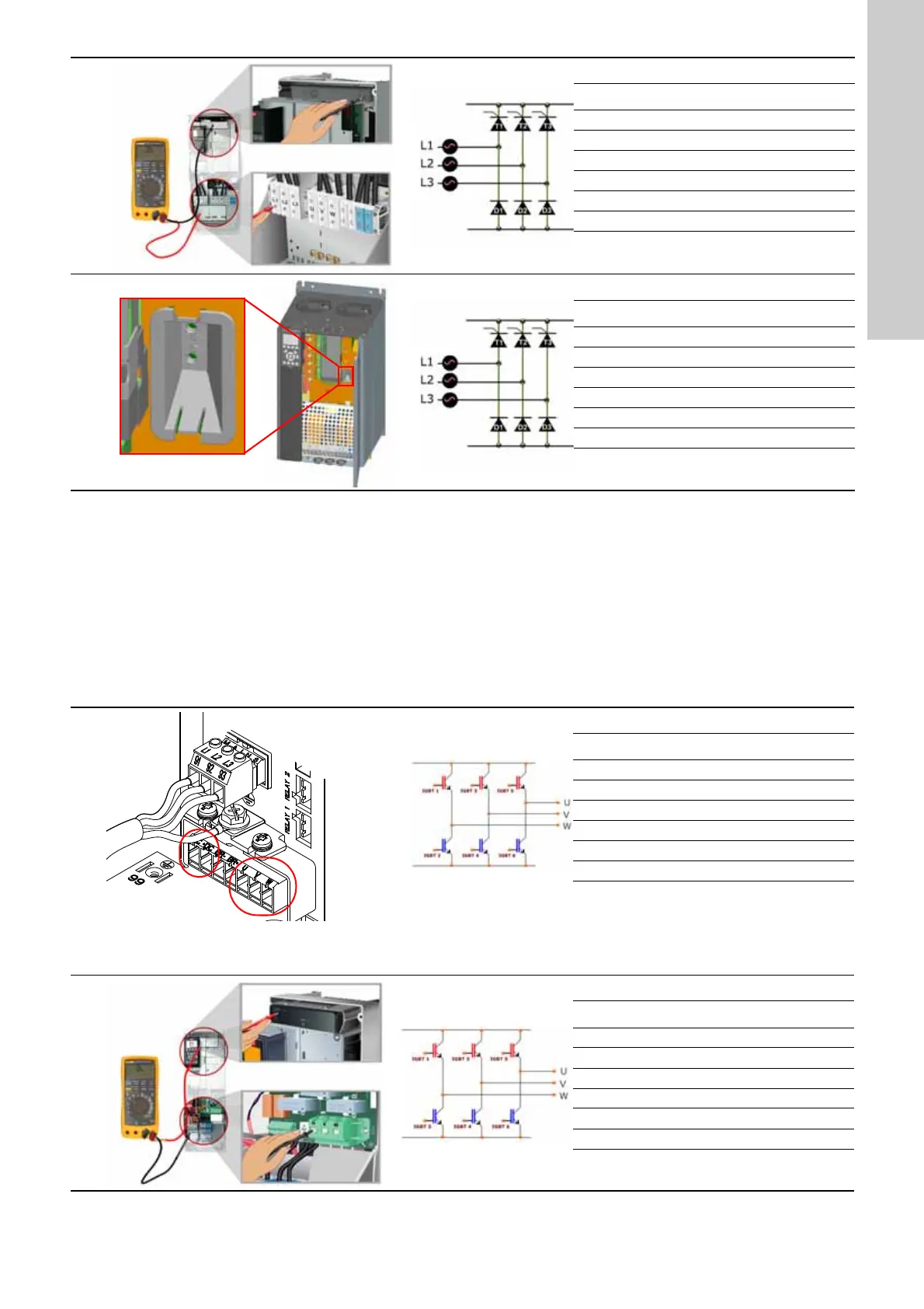
Enclosures C1, C2
Measurements
Step 1 Step 2 Step 3 Step 4
DC+ - +
DC- + -
L1 + - - +
L2 + - - +
L3 + - - +
Indication OL OL 0.4 OL
+ = positive test pin
- = negative test pin
Enclosures C3, C4
Measurements
Step 1 Step 2 Step 3 Step 4
DC+ - +
DC- + -
L1 + - - +
L2 + - - +
L3 + - - +
Indication OL OL 0.4 OL
+ = positive test pin
- = negative test pin
Enclosures A2, A3, A5, B3
TM03 9014 2807
Measurements
Step 1 Step 2 Step 3 Step 4
DC+ + -
DC- - +
U-++-
V-++-
W-++-
Indication OL 0.4 OL 0.4
+ = positive test pin
- = negative test pin
Terminals in enclosures A2 and A3 (shown with
mains supply cable connected).
Enclosures A5 and B3 have similar terminals.
Enclosures B1, B2
Measurements
Step 1 Step 2 Step 3 Step 4
DC+ + -
DC- - +
U-++-
V-++-
W-++-
Indication OL 0.4 OL 0.4
+ = positive test pin
- = negative test pin
 Loading...


