English (GB)
5
2.3 Schematic diagram
Fig. 2 Schematic diagram
2.4 Terminals
The physical position of the terminals depends on the enclosure
of CUE. See the CUE installation and operating instructions.
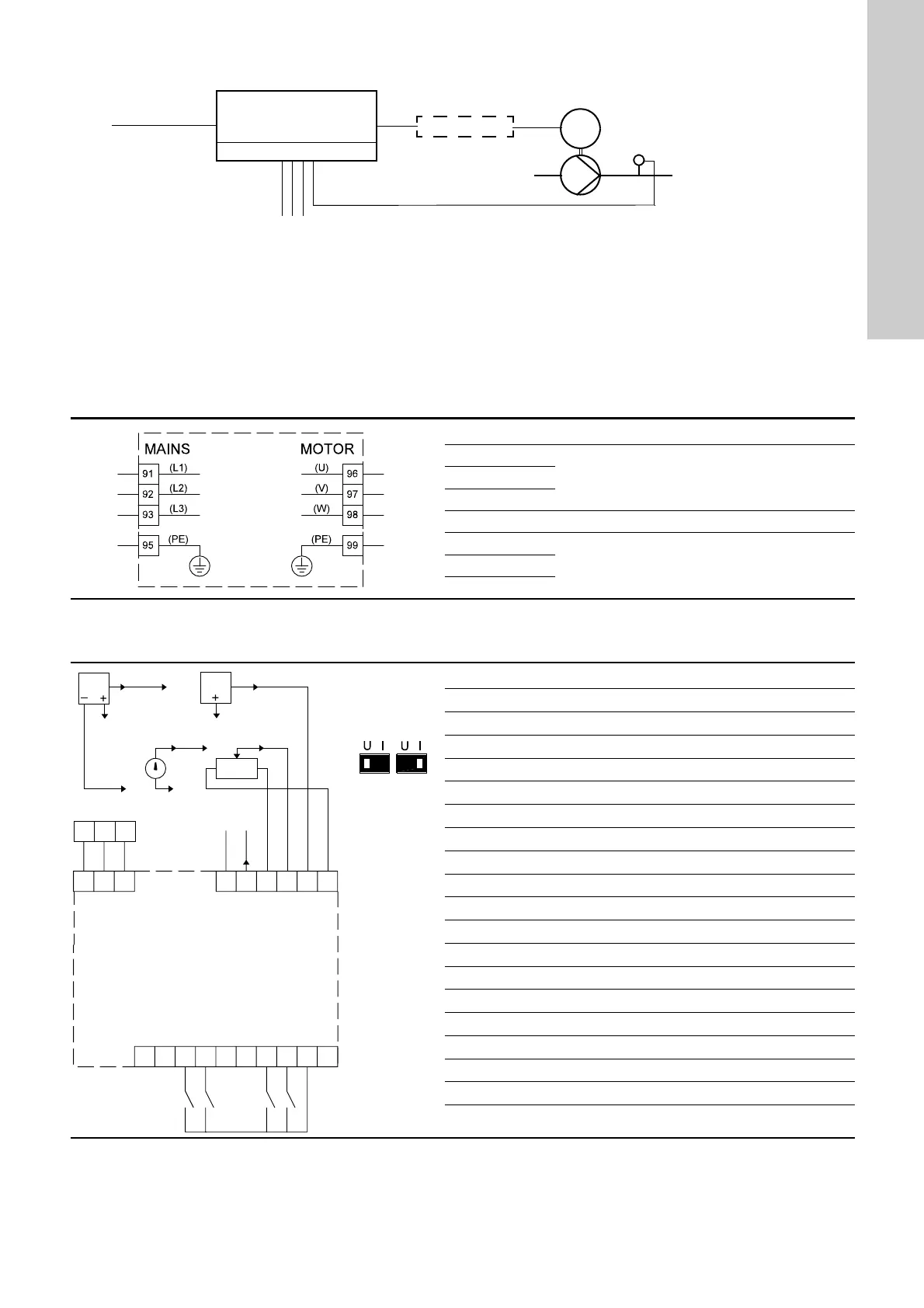
2.4.1 Mains and motor connection
The wires in the terminal box must be as short as possible.
Excepted from this is the protective earth conductor which must
be so long that it is the last one to be disconnected in case the
cable is inadvertently pulled out of the cable entry.
Fig. 3 Wiring diagram, mains and motor terminals
2.4.2 Wiring diagram, signal terminals
Fig. 4 Wiring diagram, signal terminals
Ext. I/O, relays
CUE
Filter
Supply
Sensors
External control circuit
M
TM03 8799 2507
Terminal Function
91 (L1)
Three-phase supply92 (L2)
93 (L3)
95/99 (PE) Earth connection
96 (U)
Three-phase motor connection, 0-100 % of mains
voltage
97 (V)
98 (W)
TM03 8800 3219
Terminal Type Function
12 +24 V out Supply to sensor
13 +24 V out Additional supply
18 DI 1 Digital input, programmable
19 DI 2 Digital input, programmable
20 GND Common frame for digital inputs
27 DI/O 1 Digital input/output, programmable
29 DI/O 2 Digital input/output, programmable
32 DI 3 Digital input, programmable
33 DI 4 Digital input, programmable
37 Safe stop Safe stop
39 GND Frame for analog output
42 AO 1 Analog output, 0-20 mA
50 +10 V out Supply to potentiometer
53 AI 1 External setpoint, 0-10 V
54 AI 2 Sensor input, sensor 1, 0/4-20 mA
55 GND Common frame for analog inputs
61 RS-485 GND Y GENIbus, screen (frame)
68 RS-485 A GENIbus, signal A (+)
69 RS-485 B GENIbus, signal B (-)
12
54
12
53
55
55
A54A53
61 68 69
61 68 69 42 50 53 54 5539
12 18 3720333229271913
+24 V out
+24 V out
DI 2
DI 3
DI 4
GND
GND
AO 1
+10 V out
Ext. setpoint
Sensor 1
GND
RS-485 GND Y
RS-485 A
RS-485 B
0/4-20 mA
1 K
0-20 mA
0/4-20 mA
0-10 V0-10 V
DI 1
Terminals 53
and 54
The setting
must
correspond to
the signal type
in question:
U: Voltage
I: Current
DI/O 1
DI/O 2
Safe stop

 Loading...


