EasyManuals Logo

Grundfos CUE Series Service Instructions

Grundfos CUE Series
34 pages
To Next Page IconTo Next Page
To Previous Page IconTo Previous Page
Page #6 background imageLoading...
Page #6 background image
English (GB)
6
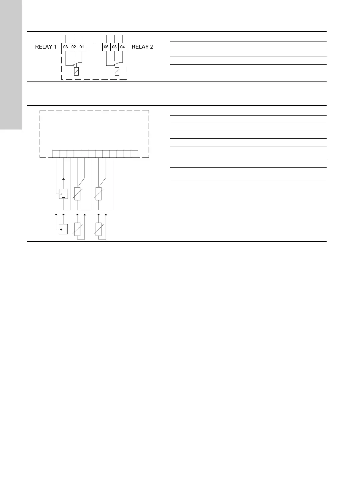
2.4.3 Connection of signal relays
Fig. 5 Terminals for signal relays in normal state (not activated)
2.4.4 Wiring diagram, MCB 114
Fig. 6 Wiring diagram, MCB 114
TM03 8801 2507
Terminal Function
C 1 C 2 Common
NO 1 NO 2 Normally open contact
NC 1 NC 2 Normally closed contact
C 1
NC 1
NO 1
NC 2
NO 2
C 2
TM07 5432 4019
Terminal Type Function
1 +24 V out Supply to sensor
2 AI 3 Sensor 2, 0/4-20 mA
3 GND Common frame for analog input
4, 5 AI 4 Temperature sensor 1, Pt100/Pt1000
6GND
Common frame for temperature
sensor 1
7, 8 AI 5 Temperature sensor 2, Pt100/Pt1000
9GND
Common frame for temperature
sensor 2
Terminals 10, 11 and 12 are not used.
1
2
3
4
5
6
7
8
9
10
11
12
0/4-20 mA
+24 V out
Sensor 2
GND
GND
GND
Temperature
sensor 1
Temperature
sensor 2
3-wire
2-wire

Other manuals for Grundfos CUE Series

Questions and Answers:

Question and Answer IconNeed help?

Do you have a question about the Grundfos CUE Series and is the answer not in the manual?

Grundfos CUE Series Specifications

General IconGeneral
CategoryDC Drives
Output Voltage24 V DC
Control Signal0-10 V, 4-20 mA
CommunicationModbus RTU
Protection FeaturesOvervoltage, overcurrent, overtemperature, short circuit
Humidity5% to 95% (non-condensing)
Enclosure classIP20
Enclosure RatingIP20

Related product manuals