Do you have a question about the Grundfos DME series and is the answer not in the manual?
Lists the various fields where the DME dosing pump is used.
Explains the coding system for pump configuration and features.
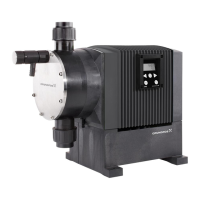
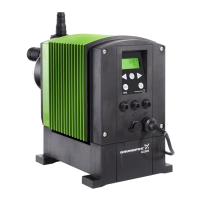
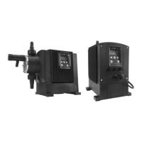
Details physical and performance specifications like capacity, pressure, and dimensions.
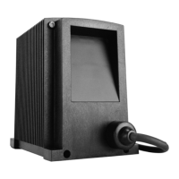
Covers supply voltage, current consumption, power, and enclosure details.
Describes the available signal inputs and outputs for pump control and monitoring.
Provides dimensional drawings and specifications for the pump.
Outlines crucial safety precautions for handling chemicals and electrical connections.
Specifies optimal conditions for pump installation, avoiding sunlight and weather exposure.
Guides on the physical mounting of the pump, including port orientation and tool usage.
Illustrates a typical installation setup of the DME pump with accessories.
Details how to properly connect the pump electrically by qualified personnel.
Shows wiring diagrams for control and level inputs, and alarm relay connections.
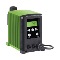
Identifies and describes the components of the pump's control panel interface.
Explains the three methods for starting and stopping the pump.
Details the procedure for priming the pump and venting air from the system.
Describes how the pump reacts to level signals from control units for tank monitoring.
Explains the function of LED indicators and the alarm relay output.
Lists available bus types for configuring the pump for fieldbus applications.
Introduces the pump's menu structure and navigation for accessing functions.
Details the five different operating modes available for the pump.
Explains the manual mode for constant dosing without external signals.
Details dosing based on external pulse signals, like from a water meter.
Describes dosing controlled by an external analog signal, proportional to mA input.
Explains batch dosing controlled by internal timers with set intervals.
Describes batch dosing triggered by external pulses from a controller.
Details the anti-cavitation function to smooth suction strokes and improve priming.
Explains how to reduce the maximum pump capacity.
Describes the non-resettable counters for quantity, strokes, hours, and power on.
Explains how to reset the pump to factory settings, including calibration.
Describes the function to return to the operating display without changes.
Lists the available languages for the display text.
Details how to configure level, stop, and analog inputs for different functions.
Explains how to select between metric and US measuring units for dosing.
Describes the dosing monitor accessory for detecting and stopping dosing faults.
Explains how to lock and unlock the control panel buttons to prevent malfunction.
Guides on calibrating the pump by measuring actual output over 100 strokes.
Explains calibration using a table of values based on counter pressure.
Details a method to verify calibration accuracy by comparing consumption and strokes.
| Protection Class | IP65 |
|---|---|
| Control type | Manual |
| Material | Stainless steel, PVDF, or PP |
| Dosing Head Material | PVDF or PP |
| Stroke Length | Adjustable |
| Type | Dosing pump |
| Power supply | 230 V, 1-phase or 400 V, 3-phase |