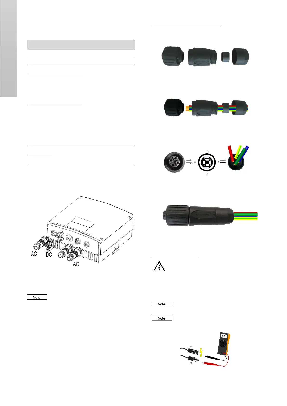
5.4.4 Electrical wiring
Fig. 12 Electrical wiring of the pump controller
Steps of electrical connection:
• If the distance between the solar inverter and the motor is
longer than 50 meters, it is recommended to install the output
choke to avoid the frequent overcurrent protection and the
motor isolation damage. For models of choke, consult
Grundfos.
• Connect the DC output, AC input, AC output and the
communication wire to the males, and then plug them to the
females of the inverter. Tighten up to ensure the proper
connection.
AC input and output connections
Follow the below steps for the connecting AC cable.
• Unscrew the terminal of all components.
Fig. 13 Connector disassembly
• Strip the cable insulation layer by about 10 mm.
• Route the cable through the connector as per fig. 14
Fig. 14 Connector disassembly
• Insert the bared wires ends as per the fig. 15
Fig. 15 Connection details
• Tighten the connection part on the left side of the connector.
Fig. 16 Connector assembly
DC input connections
Warning
Before starting the installation, ensure the following points:
• The circuit breaker between the solar panel combiner box and
solar pump controller (GI SPC) is in OFF position.
• The solar pump controller (GI SPC) is in OFF position.
Make sure that the DC input voltage from the solar
PV array to the solar pump controller does not exceed 750 VDC.
Check the solar PV array's positive and negative
terminal in multimeter, make sure that the polarity is correct as
shown in the fig. 17.
Fig. 17 Multimeter – Polarity checking
 Loading...