Installation steps of a PV pumping inverter:
• Take the installation bracket from the pump controller by only
removing the M5 screws.
• Then use expansion bolts to fix the installation bracket at the
proper location of a wall.
• Lift the inverter to suspend it on the installation bracket
through the M8 screws.
• Finally, fasten the M5 screws to fix the inverter on the bracket.
Warning
For firm installation, the operators cannot release the device
until the pump controller is installed on the bracket firmly.
Fig. 9 Pump Controller installation.
5.4 Electrical Installation
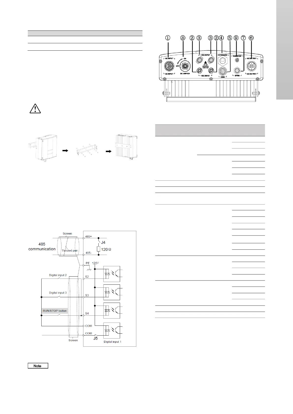
5.4.1 Control circuit wiring
The COM interfaces are the control circuit interfaces,
including one 485 communication channel and three digital
input channels. Figure 10 shows the wiring. For interface
definitions and specifications.
Fig. 10 Control circuit wiring diagram.
The Run/Stop button on the enclosure corresponds
to the S4 terminal,
5.4.2 Terminal arrangement
Fig. 11 GI SPC terminals
 Loading...