English (GB)
3
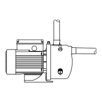
4. Identification
Fig. 1 Nameplate
5. Installation
The pump must be installed horizontally.
When the suction pipe is longer than 10 metres or
the suction lift is greater than 4 metres, the diameter
of the suction pipe must be larger than 1". If there is
a suction lift, we recommend that you fit a non-return
valve to the suction pipe.
If a hose is used as a suction pipe, it must be
non-collapsible.
To prevent solids from entering the pump, a filter can
be fitted to the suction pipe.
Make sure that the pump is not stressed by the
pipework.
Connect the discharge pipe to the pump discharge
port (T). See fig. 2. H = maximum 7 metres.
Fig. 2 Pipe connection
Installation dimensions can be found on page 10.
5.1 Handle
It is not necessary to fit the handle supplied on
permanently installed pumps.
On portable pumps the handle can be fitted
lengthwise or crosswise depending on the material
variant.
5.2 Ejector valve
The ejector valve is supplied separate with the
pump.
Remove the plug (V), see fig. 5, and fit the ejector
valve into the hole.
TM05 1797 3711
Pos. Description
1Type
2 Model
3 Supply voltage
4 Maximum current
5 Frequency
6 Maximum pressure
7 Maximum head
8 Country of origin
9 Rated head
10 Enclosure class
11 Input power
12 Rated flow rate
13 Maximum ambient temperature
14 Maximum liquid temperature
15 Efficiency class
16 Production company