Do you have a question about the Grundfos DDA 7.5-16 and is the answer not in the manual?
Explains symbols for warnings, cautions, and notes.
Highlights the need for qualified personnel for operation and service.
Emphasizes observing national regulations and pump information.
Details ensuring system safety and using monitoring functions.
Provides safety warnings when handling dosing chemicals and media.
Warns of explosion danger if liquid enters the pump housing.
Lists various areas where the pump is suitable for liquid, non-abrasive media.
Warns against improper use and operation in explosive areas.
Explains symbols found on the pump itself.
Outlines conditions for a valid guarantee claim.
Describes the information provided on the pump's nameplate.
Explains the pump's type key for identification purposes.
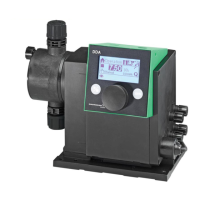
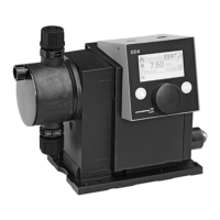
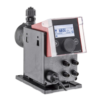
Provides a visual overview of the pump's front and rear views.
Presents detailed technical specifications and performance data of the pump.
Shows dimensional sketches and tables for pump sizing and installation.
Details steps for assembling the pump, including mounting plate installation.
Guides on connecting hoses and ensuring proper fluid flow.
Details wiring diagrams and electrical connection procedures.
Step-by-step guide to setting the pump's display language.
Instructions for removing air from the pump for optimal performance.
Explains the process of calibrating the pump for accurate dosing.
Identifies and explains the pump's control panel components.
Explains navigation, operating states, sleep mode, and display symbols.
Details the primary menus: Operation, Info, Alarm, and Setup.
Introduces the six operational modes for the pump.
Explains the manual mode for constant dosing.
Describes pulse mode for dosing based on external pulses.
Details analog, batch, and timer dosing modes.
Explains how to configure analog output signals for pump monitoring.
Details the SlowMode function to prevent cavitation.
Explains the FlowControl function for monitoring dosing process and detecting errors.
Discusses pressure sensing, setting ranges, and sensor calibration.
Describes flow measurement and AutoFlowAdapt for maintaining target flow.
Covers auto deaeration and the key lock function.
Explains display properties, units, additional display, and time/date settings.
Explains remote monitoring, activation, address setting, and fault handling.
Details configuring outputs and signal inputs.
Explains how to allocate signals to the pump's relay outputs.
Describes external stop and empty/low level signal functions.
Details daily, weekly, and monthly maintenance tasks.
Instructions for cleaning pump surfaces.
Explains how service requirements are displayed based on runtime.
Emphasizes using original parts and safety precautions during service.
Provides a diagram and labels for the dosing head components.
Step-by-step guide for dismantling the diaphragm and valves.
Instructions for reassembling the diaphragm and valves after service.
How to reset the service system after maintenance.
Warns of explosion danger if liquid enters pump housing due to diaphragm failure.
Steps to dismantle the pump safely if diaphragm is broken.
Actions to take if dosing liquid has entered the pump housing.
Guidelines for pump repairs and sending the unit for service.
Lists common faults, possible causes, and remedies.
Details specific faults displayed with error messages and their solutions.
Lists general faults, their causes, and possible remedies.
Instructions for environmentally sound disposal of the product.
Form for declaring pump cleaning status before service.
| Max Flow Rate | 7.5 l/h |
|---|---|
| Max Pressure | 16 bar |
| Protection Class | IP65 |
| Operating Temperature | 0°C to +45°C |
| Analogue Control | 4-20 mA |
| Pulse Control | Yes |
| Level Control | Yes |
| Power Supply | 100-240 V, 50/60 Hz |
| Material | Stainless Steel |