English (GB)
33
6.15 Bus communication
The bus communication enables remote
monitoring and setting of the pump via a
fieldbus system.
Further manuals, functional profiles and support files
(e.g. GSD-files) are available on the CD delivered
with the interface hardware and on
www.grundfos.com.
6.15.1 GENIbus communication
The pump is supplied with an integrated module for
GENIbus communication. The pump identifies the
bus control after connecting to the corresponding
signal input. The "Activate communication?" prompt
is displayed. After confirmation, the corresponding
symbol appears in the "Activated functions" area in
the "Operation" menu.
In the "Setup > Bus" menu the GENIbus address can
be set from 32 to 231 and bus control can be
deactivated.
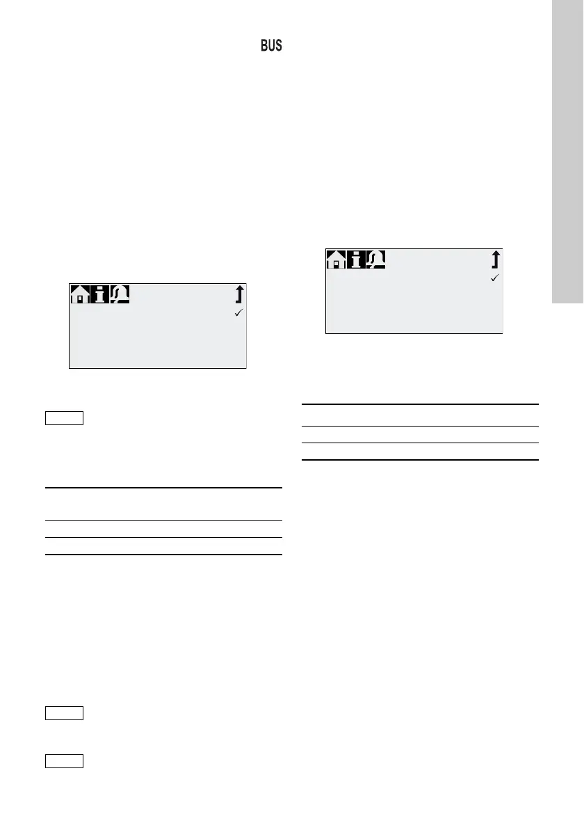
Fig. 35 Bus menu
6.15.2 Possible industrial bus types
The pump can be integrated into several networks
using the additional E-box (Extension-Box).
The pump can also be connected to a Grundfos CIU
unit (CIU = Communication Interface Unit) equipped
with one of the following CIM modules (CIM =
Communication Interface Module):
• CIM150 Profibus
• CIM200 Modbus
• CIM270 GRM
• CIM500 Ethernet
For internal communication between the E-Box/CIU
and the dosing pump, GENIbus is used.
6.15.3 Activate communication
1. Set the pump to operating state "Stop" with the
[Start/stop] key.
2. Switch off the power supply of the pump.
3. Install and connect the E-Box/CIU as described
in the respective separate installation and
operating instructions.
4. Switch on the power supply of the pump.
The "Activate communication?" prompt is displayed.
After confirmation, the "Bus" symbol appears in the
"Activated functions" area of the "Operation" menu,
no matter if the prompt was accepted or refused.
If the prompt has been accepted, the bus control
function is activated. If the prompt has been refused,
bus control function can be activated in "Setup >
Bus" menu.
Fig. 36 Example of submenu for Profibus
®
6.15.4 Setting the bus address
1. Enter "Setup > Bus" menu and set desired bus
address:
2. The pump needs to be restarted to initialise the
new bus address. Switch off the power supply of
the pump and wait for approximately 20 seconds.
3. Switch on the power supply of the pump.
The pump is initialised with the new bus address.
TM04 1139 2410
The maximum cable length for
GENIbus connection is 3 m and must
not be exceeded!
Bus type
Interface
hardware
Retrofitting possible
for pump software
Profibus
®
DP E-Box 150 V2.0 and higher
Modbus RTU E-Box 200 V2.5 and higher
The maximum cable length for
GENIbus connection is 3 m and must
not be exceeded!
Prior to installation and start-up, read
the documentation delivered with the
E-Box or CIU unit!
Bus
Bus control active
Bus address
231
TM04 1139 2410
Bus type Address range
Profibus
®
DP 0 - 126
Modbus RTU 1 - 247
Profibus
Bus control active
Bus address
126
 Loading...