English (GB)
27
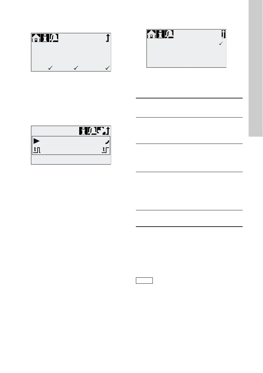
The following settings are required in the "Setup >
Dosing timer week" menu for each dosing procedure:
Fig. 29 Setting the timer
The batch volume (e.g. 80.5 ml) is set in the "Setup >
Dosing timer week" menu. The dosing time required
for this (e.g. 39.0) is displayed and can be changed.
In the "Operation" menu, the total batch volume
(e.g. 80.5 ml) and the remaining batch volume to be
dosed is displayed. During breaks in dosing, the time
(e.g. 43:32) until the next dosing is displayed.
Fig. 30 Weekly timer dosing (break in dosing)
6.5 Analog output
Fig. 31 Configure analog output
The analog output of the pump is parametrised in the
"Setup > Analog output" menu. The following
settings are possible:
* Output signal is based on motor speed and pump
status (target flow).
** Signal has same analog scaling as the current
analog input signal. See 6.4.3 Analog 0/4-20 mA.
Wiring diagram see section 4.3 Electrical
connection.
TM04 1138 1110TM04 1136 1110
Timer
Procedure
Batch volume
Dosing time[s]
Start time[hh:mm]
1
80.5ml
39.0
05:00
M ❑T TW ❑F ❑S ❑S
Operation
80.5
ml
Timer
43:32
TM04 1153 1110
Setting
Description of output
signal
Variant
FCM
FC
AR
Output =
Input
The analog input signal is
mapped 1:1 to the analog
output (e.g. to control
several pumps using one
signal)
XXX
Actual
flow**
Current actual flow
• 0/4 mA = 0 %
• 20 mA = 100 %
see section 6.9 Flow
measurement
XX*X*
Backpres
sure
Backpressure, measured
in the dosing head
• 0/4 mA = 0 bar
• 20 mA = Max.
operating pressure
see section 6.8 Pressure
monitoring
XX
Bus
control
Enabled by command in
Bus control, see section
6.15 Bus communication
XXX
In all operation modes, the analog
output has a range of 4-20 mA.
Exception: Operation mode 0-20 mA.
Here, the analog output range is
0-20 mA.
Output = Input
Actual flow
Backpressure
Bus control
❑
❑
❑
Analog out
 Loading...