Do you have a question about the Grundfos LC 109 and is the answer not in the manual?
Symbol indicating potential personal injury if instructions are not observed.
Safety guidelines for working in or near wastewater pits, emphasizing local regulations and hygiene.
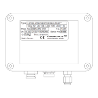
Details found on the product nameplate for identification purposes.
Crucial safety warning to switch off power supply before starting service work.
Procedures for opening isolating valves and testing functions after assembly.
Warning to ensure the controller is switched off and disconnected from mains before replacement.
Guidance on selecting a safe and suitable wall location for mounting the level converter.
Instructions to open the controller and locate the sensor connector block.
Steps to disconnect the sensor cable and remove the old sensor cable.
Instructions for removing the old level sensor and its tube from the tank.
Step for installing the new pressure tube into the tank.
Procedure to pull and secure the new sensor cable through the cable entry.
Instructions for connecting the sensor cable to the connector block as per table.
Steps for connecting the pressure hose between the level converter and the screw cap.
Final step to close the controller housing after installation.
Reconnecting power and flushing the tank to check lifting station operation.
Critical safety warning to disconnect power before any maintenance.
Information stating that electrical parts are maintenance-free.
Guidance on routine checks for mechanical parts like hoses to ensure they are fitted correctly.
Detailed steps for cleaning the pressure tube, including checking for deposits and rinsing.
| Brand | Grundfos |
|---|---|
| Model | LC 109 |
| Category | Media Converter |
| Language | English |