English (GB)
5
4. Introduction
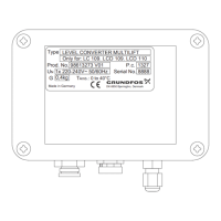
The level converter is meant to replace the current
pressure switch units of the LC 109, LCD 109 and
LC 110 controllers as these units are obsolete.
Fig. 1 Old pressure switch unit
The level converter is equipped with a piezoresistive
sensor known from the Grundfos LC 220 and LC 221
controllers. The piezoresistive pressure sensor
placed in the level converter is connected via a hose
to a pressure tube in the tank. The hose is connected
to the level converter using a bulkhead fitting. The
hose is connected to the pressure tube head at the
tank.
Fig. 2 Pressure tube, pressure tube head and
hose
The rising liquid level compresses the air inside the
pressure tube and hose, and the piezoresistive
sensor converts the air pressure into an analogue
signal.
The level converter uses the analogue signal to start
and stop the pump and to indicate high water-level
alarm.
The new level converter simulates the four switches
of the old pressure switch unit.
The table below shows the switching points of the
different Multilift units corresponding to the liquid
levels.
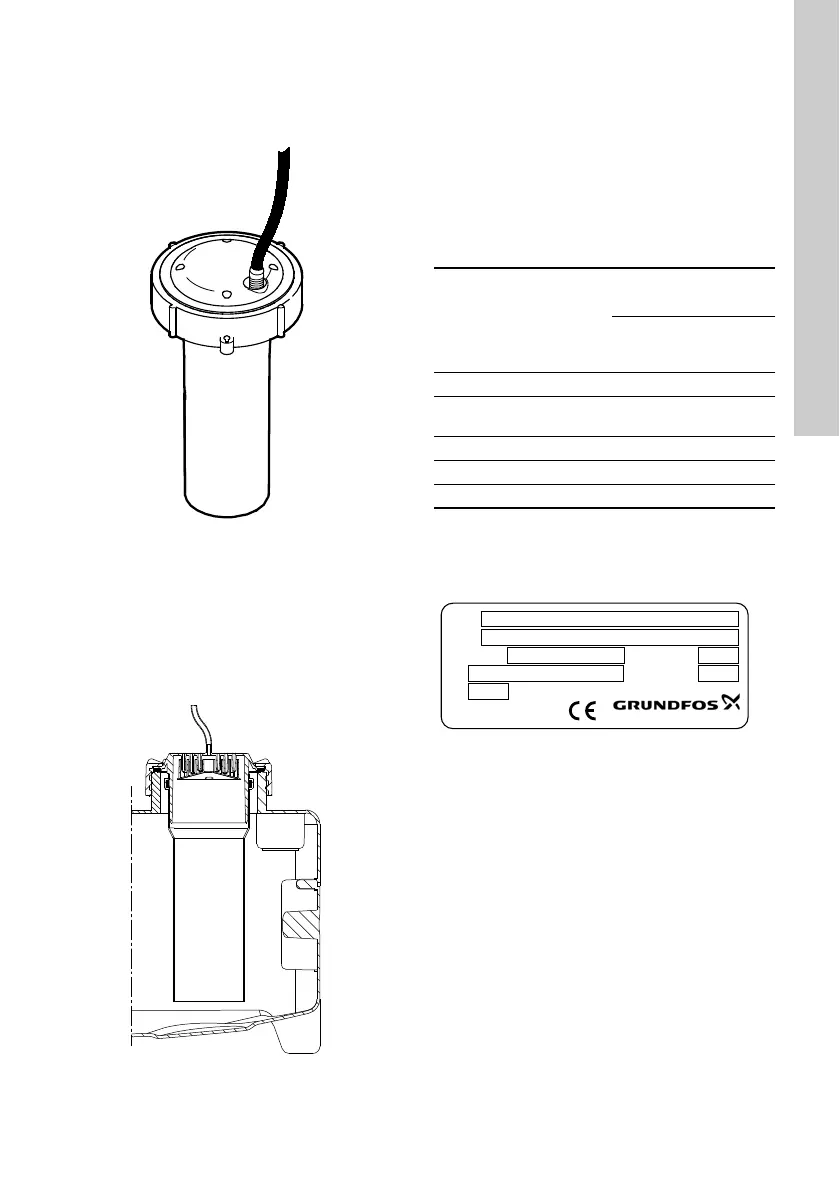
5. Identification
5.1 Nameplate
Fig. 3 Nameplate
TM02 2020 0000TM05 0332 1011
Simulated
switch
Signal
MSS,
M, MD
MLD
MD1,
MDV
Switching point
measured from floor
[mm]
S4 on Alarm 310 566 746
S3 on
Start pump 2
-250
280 516 696
S2 on Start 250 240 429 609
S1 on Start 180 160 - -
S1 off Stop 124 130 310
TM05 8891 2813
Type
U
N
G
P.c.
Serial No.
LEVEL CONVERTER MULTILIFT
Only for: LC 109. LCD 109. LCD 110
1x 220-240V~ 50/60Hz
1327
8888
0,4kg
Made in Germany
DK-8850 Bjerringbro, Denmark
Prod. No. 98613273 V01
TAmb.: 0 to 40°C
 Loading...