English (GB)
11
As an alternative to the cable sizing tool, select the
cross-section based on the current values of the
given cables.
The cross-section of the submersible drop cable
must be large enough to meet the voltage quality
requirements specified in section 5.1 General.
Determine the voltage drop for the cross-section of
the submersible drop cable with the help of the
diagrams on pages 26 and 27.
Use the following formula:
I: Rated maximum current of the motor.
For star-delta starting, I equals 58 % of the rated
maximum current of the motor.
Lx: Length of cable converted to a voltage drop of
1 % of the nominal voltage.
q: Cross-section of submersible drop cable.
Draw a straight line between the actual I-value and
the Lx-value. Where the line intersects the q-axis,
select the cross-section that lies right above the
intersection.
The diagrams are made based on the following
formulas:
Single-phase submersible motor
Three-phase submersible motor
5.4 Control of single-phase MS402
5.5 Connection of single-phase motors
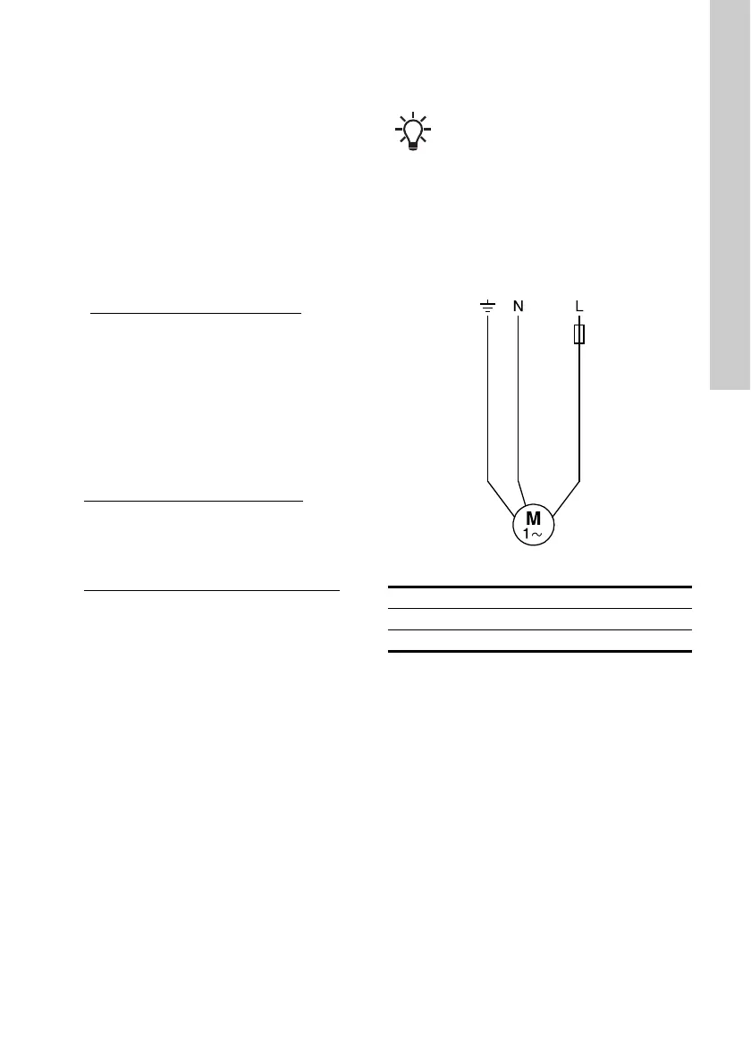
5.5.1 2-wire motors
MS402 2-wire motors incorporate motor protection
and a starter device, and can therefore be connected
directly to the mains. See fig. 8.
Fig. 8 2-wire motors
Lx =
length of drop cable
permissible voltage drop in %
L =
U × ΔU
I × 2 × 100 ×
L =
U × ΔU
I × 1.73 × 100 ×
L Length of submersible drop cable [m]
U Rated voltage [V]
ΔU Voltage drop [%]
I Rated maximum current of the motor [A]
cos φ 0.9
ρ Specific resistance: 0.02 [Ωmm
2
/m]
q Cross-section of submersible drop cable
[mm
2
]
sin φ 0.436
Xl Inductive resistance: 0.078 × 10
-3
[Ω/m].
Single-phase MS402 submersible motors
below 1.1 kW incorporate motor protection
that cuts out the motor in case of
excessive winding temperatures while the
motor is still supplied with voltage. Allow
for this when the motor forms part of a
control system.
TM00 1358 5092
1 Yellow and green
2Blue
3Brown
 Loading...