3
Grundfos Pressure Manager
General description
Introduction
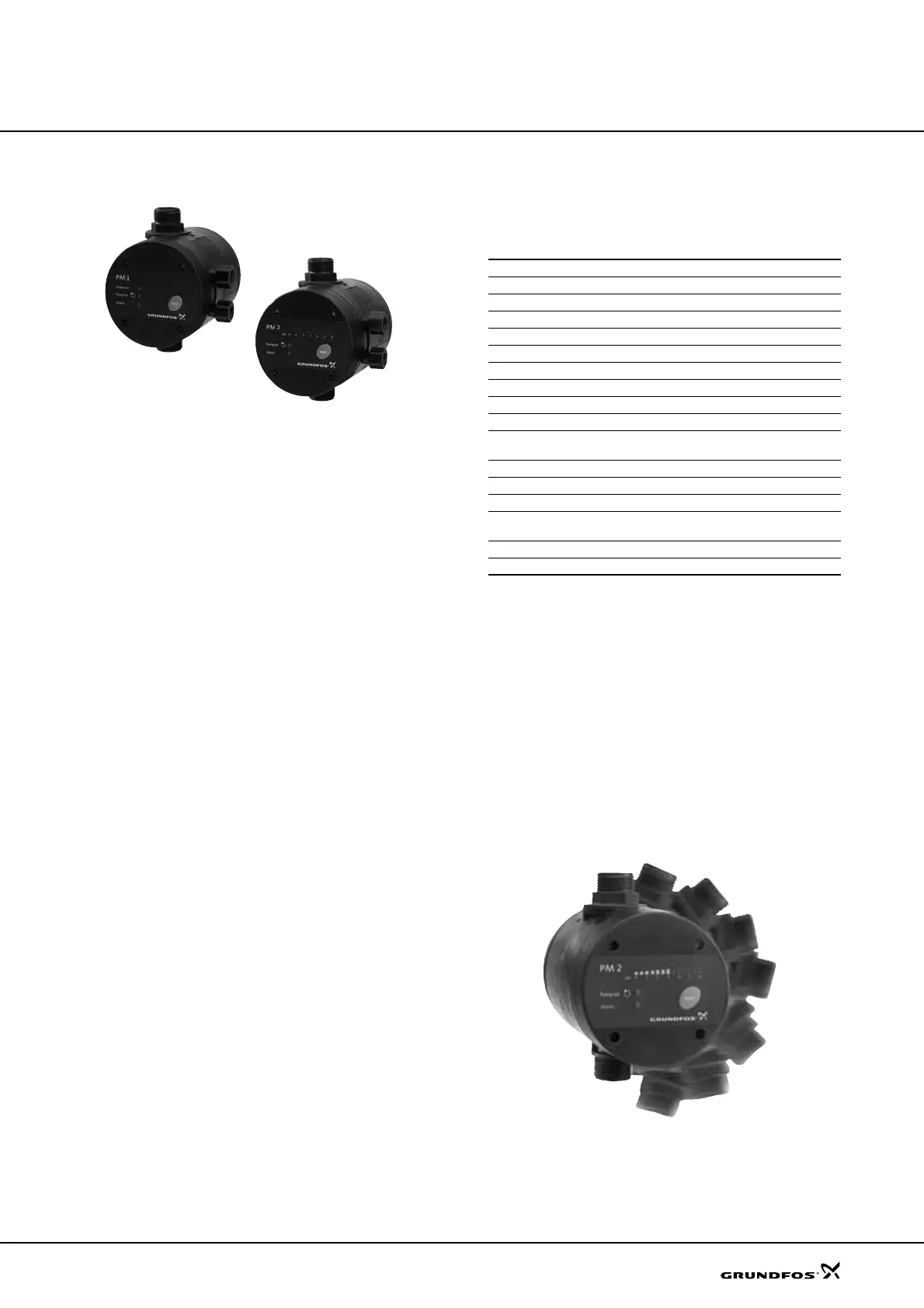
Fig. 1 Grundfos PM 1 and PM 2
The Grundfos PM 1 and PM 2 pressure managers are
designed for automatic start/stop control of Grundfos
pumps and other water supply pumps.
PM 1
The PM 1 is suitable for applications where start/stop of
the pump according to consumption is needed. It is the
basic control solution offering start at 1.5 or 2.2 bar.
The PM 1 starts the pump when the start pressure is
reached, and the pump keeps running as long as there
is a flow.
The PM 1 offers dry-running protection and cycling
alarm for increased safety.
PM 2
The PM 2 is the all-round control solution offering
adjustable start at 1.5 to 5 bar. This enables
customisation to different types of installations and
desired comfort level.
The start pressure is set by means of DIP switches
located behind the control panel whereas the current
pressure is indicated on the LED display on the front of
the PM 2.
The PM 2 starts the pump when the start pressure is
reached, and the pump keeps running as long as there
is a flow.
The PM 2 can be optimised for operation with an
external pressure tank by enabling the 1 bar
differential-pressure function. This function significantly
reduces the number of operating hours of the pump in
installations with pressure tank.
Features
The table below gives a brief comparison of the
features of the PM 1 and PM 2. The main features are
described beneath the table.
User-friendly interface
The PM 1 and PM 2 have a user-friendly interface with
LED indicators showing:
• power on
• pump running
• alarm indication
• pressure indication (only PM 2).
Free position in installation
The PM 1 and PM 2 can be freely positioned in the
installation – vertically, horizontally, or at an angle.
This makes it easier to install the units in confined
spaces and in extensive existing pipework.
Fig. 2 Free positioning of the PM 1 and PM 2
TM04 0333 0508 - TM04 0334 0508
Model PM 1 PM 2
Power-on indication zz
Pump running indication zz
Alarm indication zz
Dry-running protection zz
Free position in installation zz
Suitable for generator supply zz
Rotary outlet connection zz
Integrated non-return valve zz
Cycling alarm zz
Integrated pressure sensor from Grundfos Direct
Sensors™
z
Adjustable start pressure z
Start/stop with 1 bar differential pressure z
Automatic restarting after dry running z
Maximum continuous operating time (30 minutes)
(safety)
z
Pressure indication z
Internal pressure tank z
TM04 4913 2209

 Loading...


