Grundfos Pressure Manager
8
Installation
Mechanical installation
The PM 1 and PM 2 must be installed on the discharge
side of the pump. The PM units can be fitted directly to
the pump discharge port or between the pump and the
first tapping point.
It is recommended to connect the unit to the piping
system using unions.
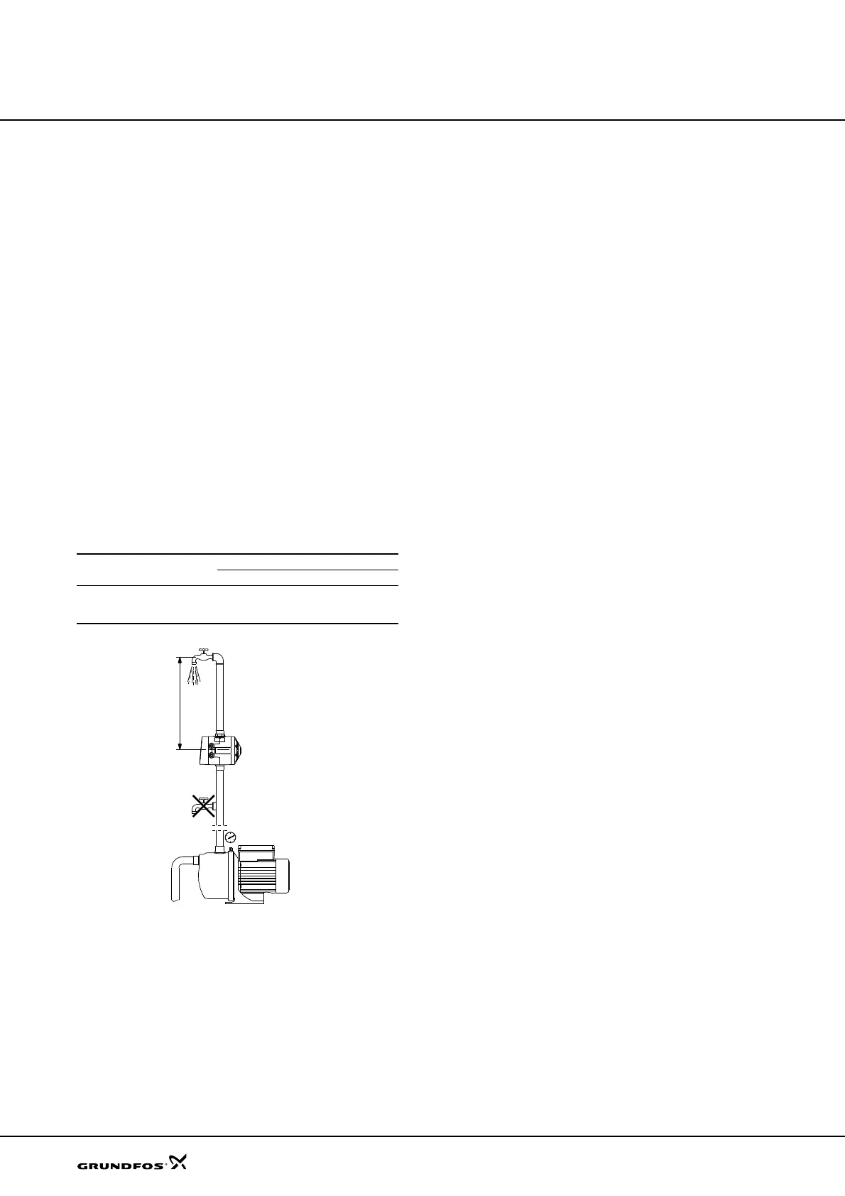
Note: No taps must be installed between the pump and
the unit.
If pumping from a well, borehole or similar, always fit
a non-return valve on the suction pipe of the pump.
Location
The installation location must be clean and well
ventilated.
The units must be positioned so that they are protected
from rain and direct sunlight.
Height between PM unit and highest tapping point
The height (H) between the PM unit and the highest
tapping point must not exceed the values in the table
below.
Fig. 8 Installation example
Electrical installation
The electrical installation must be carried out in
accordance with local regulations and standards.
• The electrical installation of the PM 1 and PM 2
must be carried out so that the enclosure class is
maintained.
• Make sure that the PM unit is suitable for the power
supply to which it will be connected.
PM type and variant
PM 1 PM 2
1.5 bar 2.2 bar 1.5 - 5 bar
Max. height (H) between
PM unit and highest
tapping point
10 metres 17 metres 45 metres
TM04 4828 2209

 Loading...


