Do you have a question about the Grundfos Sololift2 and is the answer not in the manual?
Instructions for internal cleaning of the Sololift2 when rarely used.
Procedure for cleaning connected units after Sololift2 cleaning.
Recommendations for flushing and draining the unit during long periods of inactivity.
Steps for safely removing and fitting the cover on the unit.
Detailed instructions for replacing the capacitor component.
Steps for safely removing and installing a new control board.
Guidance on how to replace the power supply cable.
Instructions for removing and fitting the pressure switch.
Comprehensive guide for replacing the motor unit.
Procedure for replacing the grinder head and impeller assembly.
Steps for removing and installing the grinder ring component.
Explanation of DIP switch settings for motor stop delay.
Steps for safely removing and fitting the cover on the unit.
Guidance on how to replace the power supply cable.
Detailed instructions for replacing the capacitor component.
Steps for removing and fitting the pressure switch.
Comprehensive guide for replacing the motor unit.
Procedure for removing and installing the impeller component.
Diagram showing the assembly of the WC-1 model.
Diagram showing the assembly of the WC-3 model.
Diagram showing the assembly of the CWC-3 model.
Diagram showing the assembly of the C-3 model.
Diagram showing the assembly of the D-2 model.
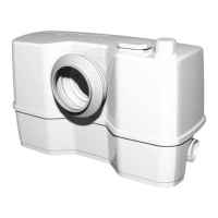
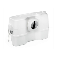
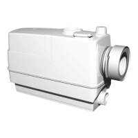
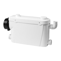
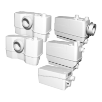
The Sololift2 is a compact and versatile lifting station designed for handling wastewater from various sanitary appliances. It is primarily used in situations where wastewater cannot be discharged directly into the main sewer system by gravity. The device is available in several models, including WC-1, WC-3, CWC-3, C-3, and D-2, each tailored for different applications and wastewater types.
The core function of the Sololift2 is to collect and pump wastewater from toilets, washbasins, showers, and other fixtures to a higher-level drain or sewer. It integrates a powerful motor, a grinder head (in WC models), an impeller, and a pressure switch within a compact tank. When wastewater enters the tank, the pressure switch detects the rising water level and activates the motor. In WC models, the grinder head macerates solid waste, such as toilet paper and human waste, into a fine slurry before it is pumped away by the impeller. For C-3 and D-2 models, which handle greywater, the impeller directly pumps the liquid. The pump continues to operate until the water level drops below a predefined threshold, at which point the pressure switch deactivates the motor. A non-return flap prevents backflow of wastewater into the connected appliances. The device is designed for intermittent operation, activating only when wastewater needs to be discharged.
The Sololift2 offers several features that enhance its usability and adaptability in various installations. Its compact design allows for discreet installation, often behind a wall, under a washbasin, or directly next to a toilet. The different models cater to specific needs:
The device is designed for easy connection to various inlet and outlet pipes. The discharge port is typically adjustable to accommodate different pipe orientations. For models with multiple inlets, flexible connections allow for easy integration with various sanitary fixtures. The control board manages the pump's operation based on the pressure switch readings, ensuring automatic and reliable wastewater removal. Some models also include DIP switches for adjusting the stop delay, offering flexibility in operation.
Maintenance of the Sololift2 is designed to be straightforward, with several features facilitating easy servicing and part replacement. The cover can be easily removed by unscrewing a single screw, providing access to internal components. Key components like the capacitor, control board, supply cable, pressure switch, motor, grinder head/impeller, and grinder ring are designed for individual replacement.
For routine cleaning, the Sololift2 can be kept clean through regular flushing of connected toilets. For less frequent use or internal cleaning, a procedure involving disconnecting power, adding detergent to the connected unit, flushing, allowing the detergent to work, and then flushing with clean water is recommended. This helps maintain hygiene and optimal performance.
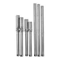
When replacing parts, the manual provides detailed instructions, including the use of specific service tools such as screwdrivers, polygrip pliers, ratchet spanners, and hexagon keys. It emphasizes the importance of switching off the power supply, closing isolating valves, and disconnecting the supply cable before any dismantling. During assembly, it is crucial to clean and check all parts, replace defective ones, and always use new gaskets and O-rings to ensure a watertight seal. Lubrication and correct tightening torques for screws and nuts are also highlighted to ensure proper reassembly and long-term reliability. The manual also includes wiring diagrams and exploded views for each model, which are invaluable resources for identifying parts and understanding the internal layout during servicing. Safety warnings regarding electrical parts and sharp edges are provided to ensure user safety during maintenance.
| Protection Class | IP44 |
|---|---|
| Protection Rating | IP44 |
| Power Supply | 230 V, 50 Hz |
| Approvals | CE |
| Outlet Diameter | DN22/25/32 |
| Housing Material | Plastic |
| Impeller Material | Plastic |