9
English (US)
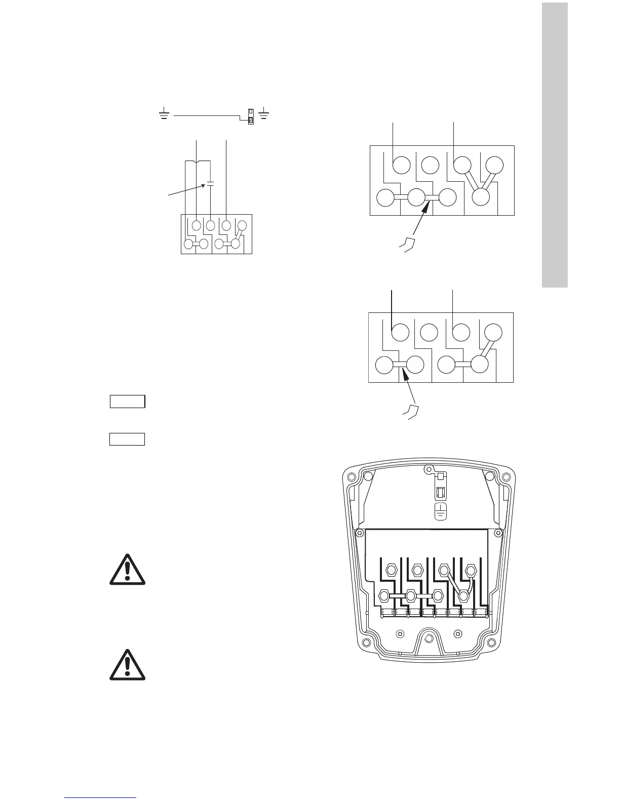
Wiring diagram
Figure 6 shows the electrical connections when
using built-in motor protection with 1 x 230 V
supply.
Fig. 6 Electrical connections (1 x 230 V
supply)
5. Starting the pump
5.1 Vent the piping system
After the pump has been installed and the
electrical connections made, the piping system
must be vented.
Instead, follow these steps:
1. Fill and pressurize the system with liquid,
and vent all trapped air from the piping by
suitable means.
2. If isolation valves are used, make sure they
are OPEN.
5.2 Voltage selection
Change the pump input voltage as follows:
The voltage is changed by the position of the
jumpers in the terminals. The jumpers are fitted
according to:
• figure 7 for 115 V AC
• figure 8 for 230 V AC.
Fig. 7 Jumper position for 115 V AC
Fig. 8 Jumper position for 230 V AC
Fig. 9 Terminal box
TM03 7297 4706
Do not vent the piping system
through the pump.
Warning
If the vent screw is to be loosened,
care should be taken to ensure that
the escaping scalding hot liquid
does not cause personal injury or
damage to components.
Warning
Never make any connections in the
pump terminal box unless the
power supply has been switched
off.
 Loading...