Page 4
If the terminal box position needs to be changed, ensure
that the electrical supply is turned off and close the
isolation valves before removing the Allen screws.
To change control box position:
• Remove the four (4) Allen screws (4 or 5mm
wrench) while supporting the stator (motor).
• Carefully separate the stator from the pump
chamber and rotate it to the correct terminal box
orientation.
• Replace the Allen screws and tighten diagonally
and evenly (7 ft. –lb. torque).
• Check that the motor shaft turns freely. Remove
the large screw in the middle of the nameplate,
insert a small flat blade screwdriver into the end of
the shaft, and turn gently.
• If the shaft does not turn easily, repeat the disas-
sembly/reassembly process.
Arrows on the side or bottom of the pump chamber
indicate direction of flow through the pump.
Page 6
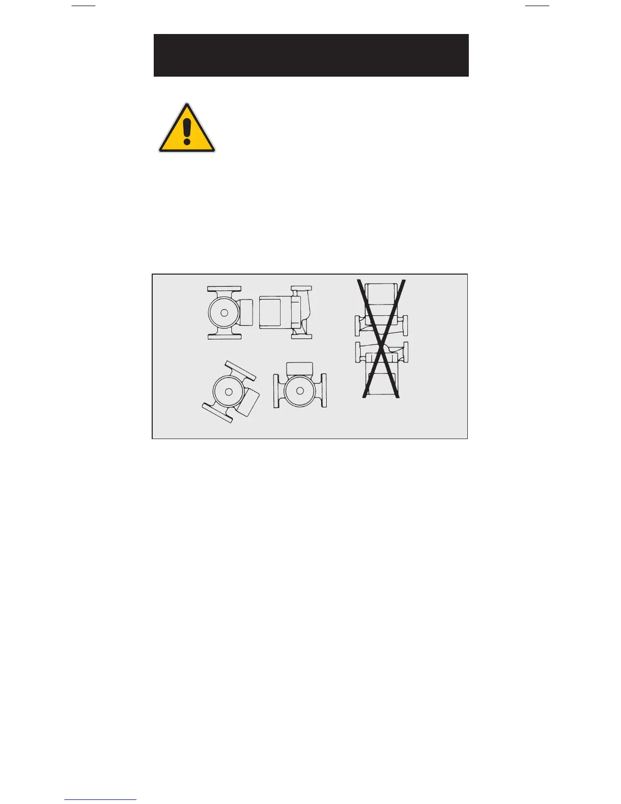
Recommended
Optional
DO NOT
Mount Motor Shaft
in Vertical Position
Figure 1
Warning: Consult piping manufactures
for material selection before installing
this pump. Absence of pumping fluid
may damage some piping materials.
Caution: Thoroughly clean and flush the system prior
to pump installation
For Indoor Use Only
Preferred Pump & Terminal Box Orientation:
4.
Pump Installation
 Loading...