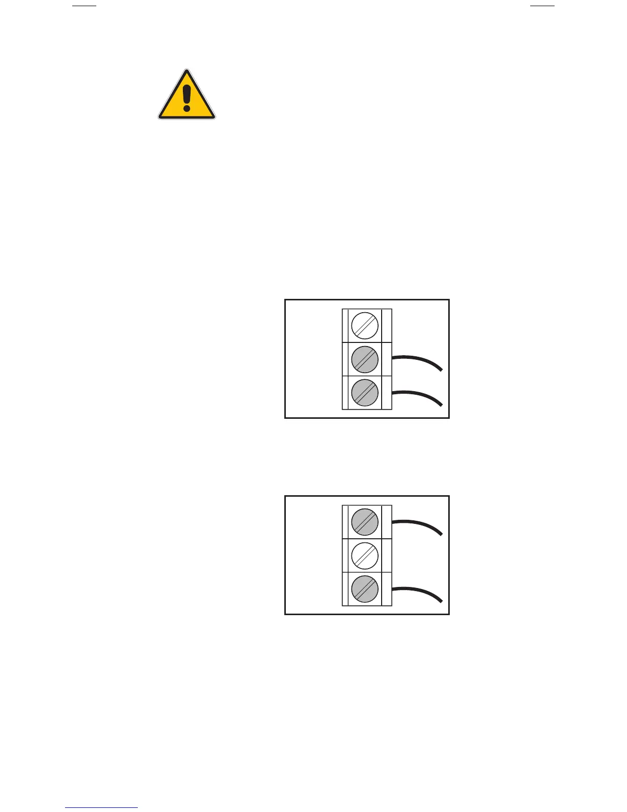
Figure 3 - Current
connections to the
(Com(-) & Ret/I)
control
Figure 4 - Voltage
connections to the
(Com(-) & Os/V)
control
Voltage Speed Control Signal Connections:
Connect the voltage signal wires to terminals
“Com(-)” and “Os/V” (Fig 4.).
Electrical Connections To The Control:
CAUTION: The installer should confirm
that no current/voltage is present at any
of the wires.
Current Speed Control Signal Connections:
Connect the current signal wires to terminals
“Com(-)” and “Ret/I” (Fig 3.).
Test the Speed Control Signal Wiring.
Make sure exposed wires and bare terminals are
not in contact with other wires or grounded
surfaces. Turn on the control signal and measure
the voltage/mA across the leads using a voltmeter
to confirm the pump signal is present.
Note: Control signal wires must be run through and
secured by the stain relief on the terminal board.
Note: No speed control signal is necessary if speed
is to be regulated using the manual % dial.
 Loading...