Control modes, user interface and settings
18
Medium UPM
6
User interface
Externally controlled versions
Externally PWM controlled Medium UPM pumps have
no user interface. LIN versions have a red and green
LED for indication of fault and communication.
AUTO versions
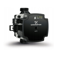
Internally controlled Medium UPM AUTO pumps have
a user interface with one button and three LEDs.
Fig. 19 UPM AUTO user interface
The user interface allows to select between 8 control
curves in two control modes:
• 3 proportional pressure curves (PP) plus
AUTO
ADAPT
PP
• 3 constant pressure/power curves (CP) plus
AUTO
ADAPT
CP
Fig. 20 Manual curve setting
Fig. 21 Serial curve setting
The first time, the pump starts with the factory
presetting: Proportional pressure curve, PP2.
• Push the button for 2 seconds:
– the pump goes to setting mode - LED starts
flashing.
• With each push, the setting changes:
– LEDs 1-2-3 are permanently on, the control curve
and mode are changed.
• Flashing mode:
– Fast: Proportional pressure
– Slow: Constant pressure/power
• If the button is not pushed for ten seconds:
– the setting is adapted.
– the pump returns into operating mode
During operation, the display shows the selected
setting.
• LED 1 or 2 or 3 is permanently on.
– Pump is running with the selected curve and
mode.
TM07 2009 2518
TM07 1791 2218TM07 1422 2518
PP1 PP2 PP3
CP1CP2CP3
PPAA
CPAA
CP = PP =
PP
CP
1 click
1 click
Hold 2 sec.

 Loading...

