Do you have a question about the Grundfos UPE 50-120 and is the answer not in the manual?
Details on where the UPE Series 2000 pumps can be used in heating and hot-water systems.
Specifies suitable liquids and water quality requirements for UPE pumps in various systems.
Guidance on rotating the terminal box to different installation orientations.
Step-by-step procedure for reorienting the pump head and terminal box.
How to adjust the nameplate position after changing the terminal box orientation.
Considerations for installing a non-return valve to ensure adequate pump performance.
Advice on pump insulation to prevent sensor coverage and ensure proper function.
Procedures to protect the pump from damage during periods of frost.
Specifies the correct supply voltage and frequency for pump operation.
Explanation of Proportional Pressure and Constant Pressure control modes.
Guidance on choosing the most suitable control mode based on system needs.
Pre-set values for control mode and head based on pump model at the factory.
Overview of the control panel's buttons, indicators, and light fields.
How to select and change the pump's operating control mode via the panel.
Adjusting the desired head and selecting operating modes like Stop, Min., or Max.
Choosing the pump's operational mode and its source (Pump, R100, BUS, External).
Viewing current pump faults, their causes, and potential remedies.
Shows the current pump setpoint and its percentage value relative to the maximum.
Displays the active operating mode and where it was configured.
Real-time display of the pump's current head and flow rate.
Shows the current rotational speed of the pump's motor.
Indicates the temperature of the fluid being pumped.
Displays current power usage and accumulated energy consumption.
Shows the total accumulated operating time of the pump.
Selecting the primary control mode: Proportional, Constant, or Constant Curve.
Choosing between two minimum performance curves for pump operation.
Activating and setting the temperature influence feature for head adjustment.
Locking or unlocking the control panel buttons for security purposes.
Allocating a unique number for pump identification in control systems.
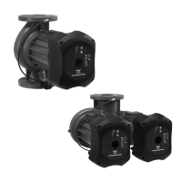
Setting for twin-head pumps, differentiating single and twin operation modes.
Instructions for conducting high-voltage tests on UPE pumps.
| Head | Up to 12 m |
|---|---|
| Maximum Operating Pressure | 10 bar |
| Model | UPE 50-120 |
| Max Head | 12 m |
| Pump Type | Circulator pump |
| Power Supply | Single-phase |
| Liquid Temperature Range | -25 .. 120 °C |
| Approvals | CE |
| Pump Housing | Cast Iron |
| Frequency | 50 Hz |
| Material | Cast Iron |
| Operating Temperature | -25 .. 120 °C |
| Supply Voltage | 230 V |
| Voltage | 230 V |