English (US)
12
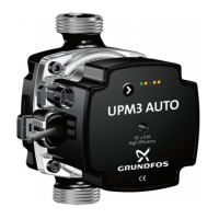
Flow estimation (option)
The PWM feedback signal can be used to measure the flow of the
pump.
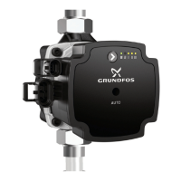
Fig. 13 PWM feedback signal
6.2.2 0-10 VDC
GRUNDFOS UPML and UPMXL circulators are externally speed-
controlled by a analogue 0-10 V DC signal. The pump requires a
0-10 V signal on the signal port to control the speed of the pump.
The pump will run at its minimum speed, if the signal fails (cable
break).
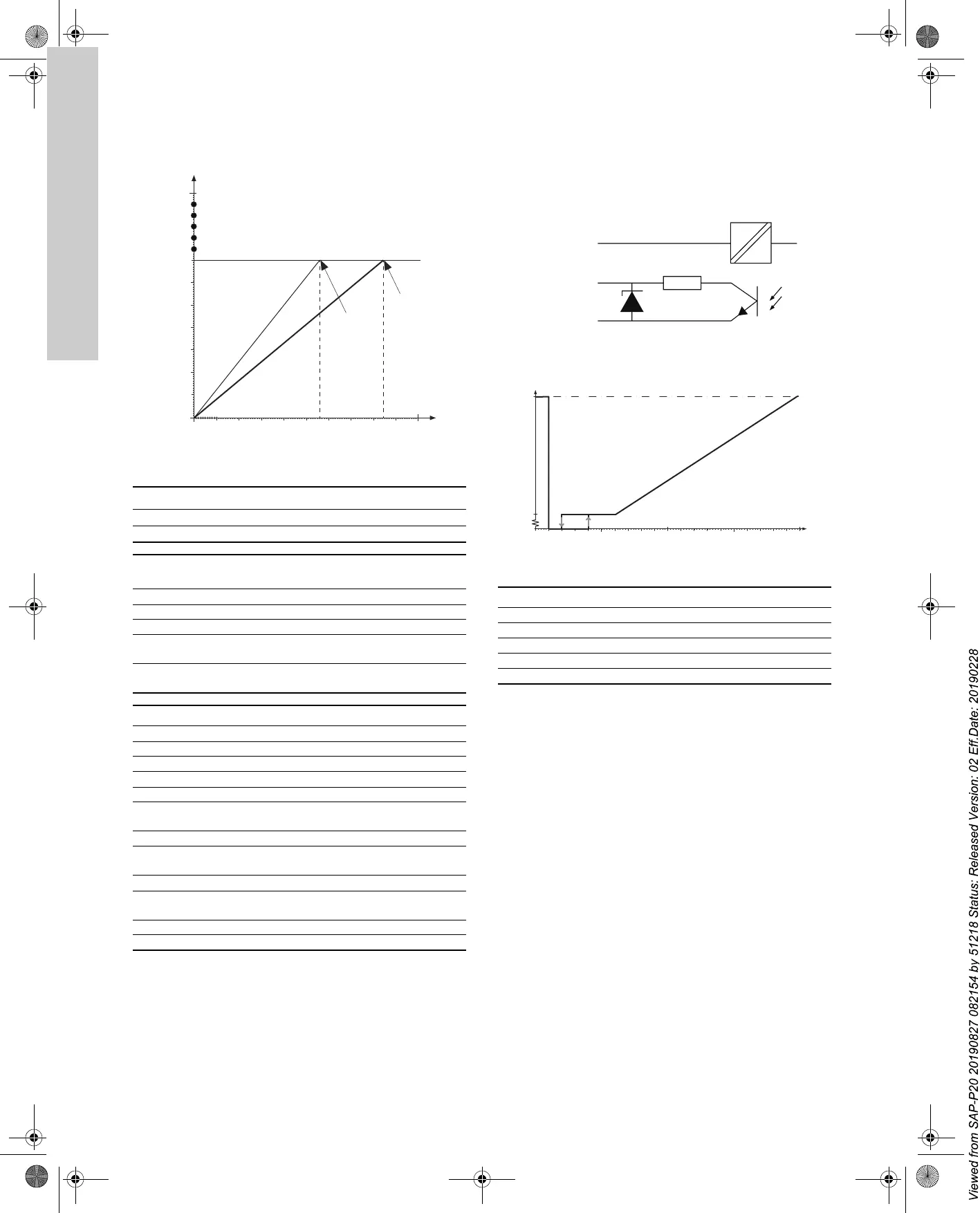
Profile R
Fig. 14 Profile R
TM07 0596 0518
Pos. Description
1 UPML saturation point, 140 W
2 UPMXL saturation point, 210 W
PWM output
signal [%]
Indicates Pump operation
95 Standby Stop
90 Rotor blocked Stop
85 Undervoltage stop Stop
75
Undervoltage warning
at Un -15 %
Pump performance is
reduced from Un -10 %.
0-70 Power [W]
Pump is running
according to setpoint.
Rating Value
Rated input voltage - high level U
IH
4-24 V
Rated input voltage - low level U
IL
< 1 V
High-level input current I
IH
< 10 mA
Input duty cycle PWM 0-100 %
PWM frequency output, open collector f 75 Hz ± 5 %
Accuracy of output signal regarding
power consumption
-
± 2 % of PWM
signal
Output duty cycle PWM 0-100 %
Collector-emitter breakdown voltage
on output transistor
U
C
< 70 V
Collector current on output transistor I
C
< 50 mA
Max. power dissipation on output
resistor
P
R
125 mW
Zener diode working voltage U
Z
36 V
Max. power dissipation in Zener diode P
Z
300 mW
25 50 100 150 200 250
10
20
30
40
50
60
70
80
90
100
1
2
Standby (stop)
Alarm stop: Fault, blocked pump
Alarm stop: Electrical fault
Warning
PWM output [%]
Output frequency: 75 Hz ± 5 %
Power [W]
S
l
o
p
e
:
3
W
/
%
S
l
o
p
e
:
2
W
/
%
TM07 0439 5017TM07 0784 0518
U [V] Pump status
U <= 0.5 MAX speed
0.5 < U <= 1 Standby (STOP)
1 < U <= 2 Hysteresis
2 < U <= 3 MIN speed
3 < U <= 10 Speed between MIN and MAX
Signal input
Signal output
Signal ref
UPMM_UPML_UPMXL_US.book Page 12 Tuesday, February 26, 2019 10:18 PM