Appendix
28
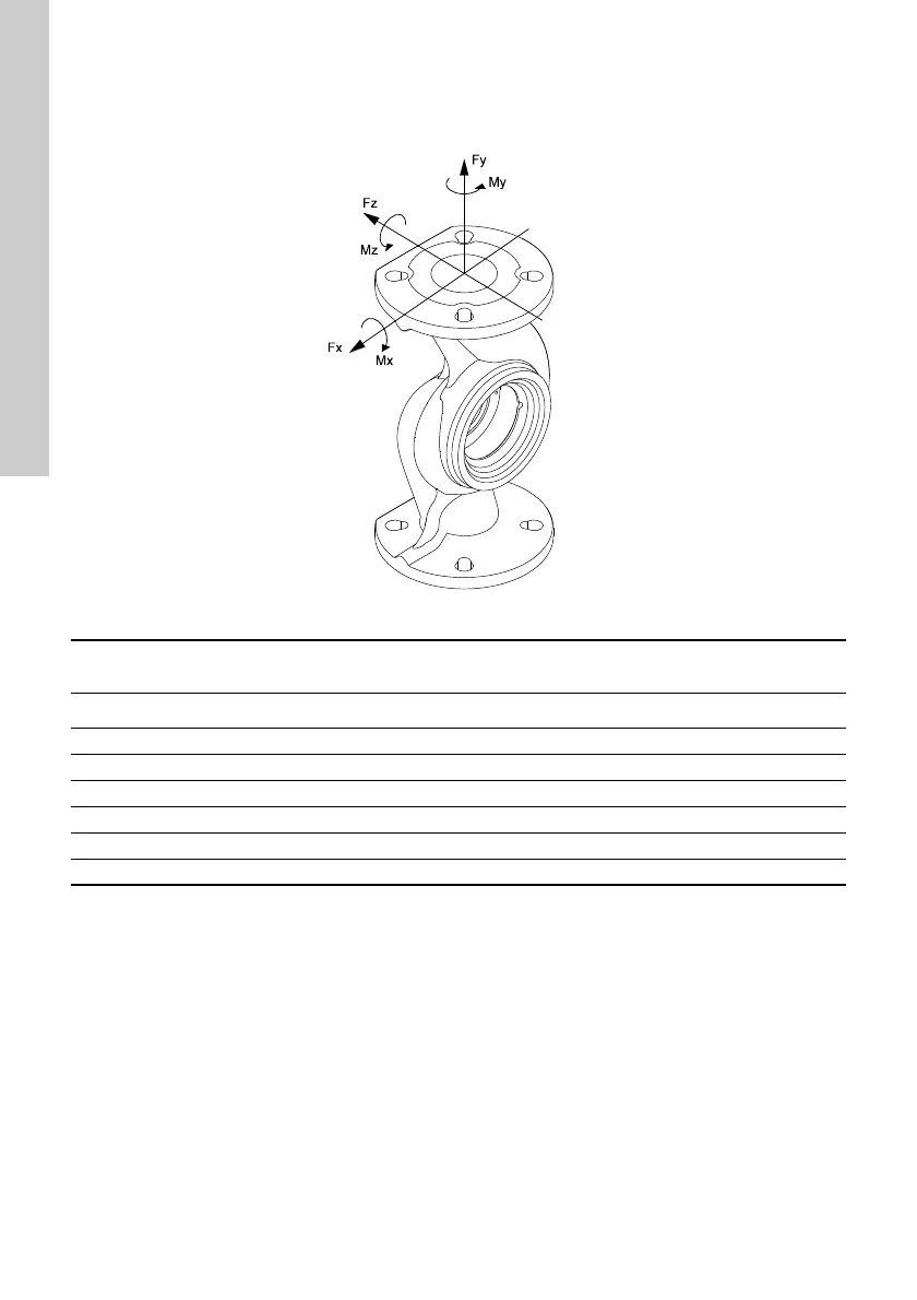
Flange forces and moments
For maximum permissible forces and moments from the pipe connections acting on the pump
flanges or thread connections, see fig. 21.
Fig. 21 Flange forces and moments
Above values apply to cast iron and brass versions. See ISO 5199, tables B.2 (16A and 16B), B.3 and B.6.
TM05 5639 3912
Force
[N]
Moment
[Nm]
Diameter, DN Fy Fz Fx ΣFb My Mz Mx ΣMb
32 425 525 450 825 375 425 550 800
40 500 625 550 975 450 525 650 950
50 675 825 750 1300 500 575 700 1025
65 850 1050 925 1650 550 600 750 1100
80 1025 1250 1125 1975 575 650 800 1175
100 1350 1675 1500 2625 625 725 875 1300
 Loading...