English (GB)
14
7. Setting the product
7.1 Constant curve I, II, III
To set the product to constant curve I, II or III use the push-button
on the operating panel. Every time you press the push-button, the
pump setting is changed. The loop consists of four button
presses. The LEDs will indicate the chosen control mode. See fig.
19.
To learn more about each control mode, see section 6.2 Control
modes.
7.2 Proportional pressure I, II and constant pressure
mode I, II
To select a proportional-pressure or constant-pressure curve,
press and hold the push-button for 3 seconds. The LEDs will
indicate proportional pressure I. See fig. 19.
Press the push-button until you have set the pump to the desired
control mode. The loop consists of four button presses. The LEDs
will indicate the chosen control mode. See fig. 19.
To return to constant-curve settings, press and hold the button for
3 seconds.
To learn more about each control mode, see section 6.2 Control
modes.
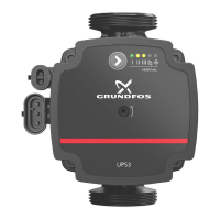
Fig. 19 Operating panel LEDs indicating the different control modes
7.3 Setting the PWM input signal
To enable the external control mode (PWM profile A), you need a
signal cable connected to an external system. The cable
connection has three conductors: the signal input, the signal
output and the signal reference.
The cable is not supplied with the pump but can be ordered as an
accessory.
Fig. 20 Mini superseal plug
Set the signal connection
1. Make sure that the pump is turned off.
2. The PWM signal connection is covered by a blind plug.
Remove the plug.
3. Connect the signal cable with the mini superseal plug.
4. Switch on the power supply.
5. The pump automatically detects if a valid PWM signal is
available after which it enables the control mode on the pump.
See fig. 21.
Fig. 21 Connecting the signal cable to the UPS3
The pump is factory set to constant curve III.
TM07 0144 4817
 Loading...