English (GB)
3
1.2 Notes
The symbols and notes below may appear in Grundfos
installation and operating instructions, safety instructions and
service instructions.
2. Receiving the product
2.1 Inspecting the product
Check that the product received is in accordance with the order.
Check that the voltage and frequency of the product match
voltage and frequency of the installation site. See section
5.4.1 Nameplate.
2.2 Scope of delivery
The box contains the following items:
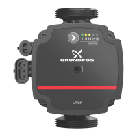
• UPS3 pump
• installer plug
• two gaskets
• quick guide.
3. Installing the product
3.1 Mechanical installation
3.1.1 Mounting the product
1. The arrows on the pump housing indicate the flow direction
through the pump. See fig. 1.
2. Fit the two gaskets supplied with the pump when you mount
the pump in the pipe. Install the pump with a horizontal motor
shaft. See fig. 2. See also section 3.3 Control box positions.
3. Tighten the fittings. See fig. 3.
Fig. 1 Flow direction
Fig. 2 Pump installation
Fig. 3 Tightening the fittings
Observe these instructions for explosion-proof
products.
A blue or grey circle with a white graphical symbol
indicates that an action must be taken.
A red or grey circle with a diagonal bar, possibly with
a black graphical symbol, indicates that an action
must not be taken or must be stopped.
If these instructions are not observed, it may result in
malfunction or damage to the equipment.
Tips and advice that make the work easier.
TM07 0368 1518TM07 0369 1518TM07 0370 1518
 Loading...