English (GB)
4
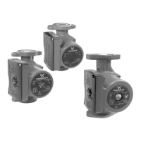
3.2 Pump positions
Always install the pump with a horizontal motor shaft. Do not
install the pump with a vertical motor shaft. See fig. 4, bottom row.
• Pump installed correctly in a vertical pipe. See fig. 4, top row,
left.
• Pump installed correctly in a horizontal pipe. See fig. 4, top
row, right.
Fig. 4 Pump positions
3.3 Control box positions
The control box can be mounted in all positions. See fig. 5.
Fig. 5 Possible control box positions
3.3.1 Changing the control box position
3.4 Insulating the pump housing
Fig. 6 Insulating the pump housing
You can reduce the heat loss from the pump and pipe by
insulating the pump housing and the pipe with insulating shells,
which can be ordered as an accessory. See section
5.5.2 Insulating shells.
TM07 0371 1518
DANGER
Electric shock
Death or serious personal injury
- Switch off the power supply before starting any
work on the product. Make sure that the power
supply cannot be accidentally switched on.
CAUTION
Hot surface
Minor or moderate personal injury
- The pump housing may be hot due to the pumped
liquid being scalding hot. Close the isolating valves
on both sides of the pump and wait for the pump
housing to cool down.
CAUTION
Pressurised system
Minor or moderate personal injury
- Before dismantling the pump, drain the system or
close the isolating valves on both sides of the
pump. The pumped liquid may be scalding hot
and under high pressure.
TM06 7297 0918
Step Action Illustration
1
Make sure that
the inlet and
outlet valves are
closed.
Unscrew the
screws on the
pump head.
TM07 0372 1518
2
Turn the pump
head to the
desired position.
TM07 0373 1518
3
Refit the screws
on the pump
head.
TM07 0374 1518
TM07 0375 1518
Do not insulate the control box or cover the operating
panel.
 Loading...