Einstellvorschriften / Adjustment Procedures CCF 23
2 - 4 GRUNDIG Service
Adjustment Procedures
Measuring instruments/equipment:
Frequency counter, AF voltmeter, DC voltmeter, AF generator, distortion analyzer, wow and flutter meter,
Cr test cassette 448 A (part no. 35079-023.00), torque test cassette 456 (part no. 35079-014.00).
Layout of adjustment controls see page 2 - 3. Adjustment of the tape transport see page 2 - 6. The symbol refers to a point in the circuit diagram.
1. Tape speed
Deck A/B
2. Take-up torque
on Start
Deck A/B
3. Wow and flutter
Deck A/B
4. Head gap angle
(Azimuth)
Deck A/B
5. Playback level
Reference tape
scanning
(Dolby level)
Deck A/B
6. Erase frequency
Deck B
7. Erase current
Deck B
8. HX-PRO
Deck B
9. Record blocking
circuits
(bias filter)
1. High Speed adjustment: With adjustment control R566
(Deck A) or R561 (Deck B) set the frequency to 6300Hz
± 0.1% .
2. Normal Speed adjustment: With adjustment control
R564 (Deck A) or R558 (Deck B) set the frequency to
3150Hz ± 0.1%.
On START, the torque should be 25 to 70 x 10
-4
Nm
≈ 40g-cm.
Deviation < 0.13% (IEC wtd). Playback measuring time
≥ 30 seconds.
Deck A+B
Tape direction: "Normal"
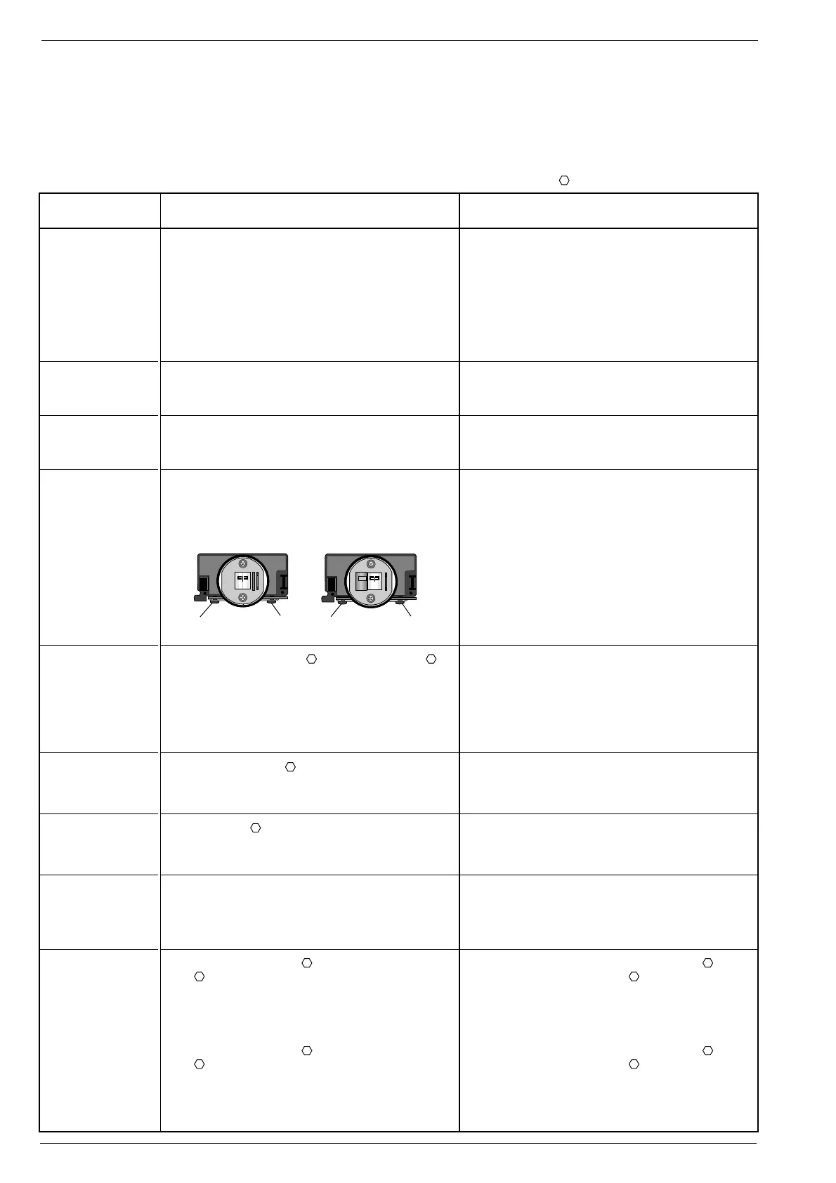
With the head adjustment screw 1 set the left or right
channel to maximum level.
Then connect the left channel in parallel with the right
channel (LINE OUT). By minimum re-adjustment of the
head adjustment screw 1 set the output level to maximum.
Turn around the test cassette.
Tape direction: "Reverse"
Adjustment with head adjustment screw 2 is the same as
in the "Normal" tape direction.
Deck B:
With R156 (left), R157 (right) for Deck B and with R154
(left), R155 (right) for Deck A set a playback level of
490mV ± 0.5dB (LINE OUT ≈ 950mV).
When using a test cassette with 200nWb/m set the playback
level to 388mV ± 0.5dB (LINE OUT ≈ 750mV).
The oscillator frequency should be 85kHz ± 10kHz .
Adjust with L103.
Erase current: 150mA ± 10%
measured at R253 = 150mV ± 10%.
Adjust for minimum DC voltage with L104 at pin13 IC105
(right channel) and with L105 at pin 6 IC105 (left channel).
Adjust for minimum RF with F200 at test point D1 (left
channel) and F210 at test point D2 (right channel).
Adjust for minimum RF with F106 at test point D3 (left
channel) and F105 at test point D4 (right channel).
Adjustment Preparations Adjustment Procedure
Frequency counter to LINE OUT.
Insert test cassette 448 A in Deck A and Deck B respectively,
play back 3150Hz.
1. High Speed adjustment:
- Playback on Deck A and Deck B respectively.
- Short-circuit base + emitter of transistor T523.
2. Normal Speed adjustment:
Playback on Deck A and Deck B respectively.
Load the torque test cassette 456 (Deck A/B).
Function: Start
Wow and flutter meter to LINE OUT.
Load test cassette 448 A (Deck A/B).
Play back 3150Hz
Connect AF-voltmeter to LINE OUT L (left channel) and to
LINE OUT R (right channel) respectively.
Load test cassette 448 A (Deck A and Deck B respectively),
play back 10kHz.
PB-head Deck A R/PB-head Deck B
AF-voltmeter to test point D1 (left channel) or D2
(right channel).
Insert test cassette 448 A (Deck A and Deck B respectively).
Play back 315Hz (250nWb/m).
Dolby off
Adjust Deck B first.
Frequency counter to L1 (R253).
Insert a recordable cassette, Cr tape (IEC II).
Function: Record-Start
AF-voltmeter to TP (in parallel with R253).
Insert a recordable cassette with Cr tape (IEC II).
Function: Record-Start
DC-voltmeter to Pin13 IC105 (right channel) and to Pin6
IC105 (left channel) respectively.
Insert a recordable cassette Cr tape (IEC II) in Deck B.
Function: Record-Start, Dolby off
AF-voltmeter to test point D1 (left channel) and to test
point D2 (right channel) respectively.
Insert a blank cassette in Deck A.
Insert a recordable cassette Cr tape (IEC II) in Deck B.
Function: High Dubbing
AF-voltmeter to test point D3 (left channel) and to test
point D4 (right channel) respectively.
Function: High Dubbing
k
2
1 1
2


 To Next Page