EasyManua.ls Logo

Grundig R 1000 DPL User Manual

Grundig R 1000 DPL
66 pages
Go to English
To Next Page IconTo Next Page
Page #1 background imageLoading...
Page #1 background image
GRU
MDG
service
manuat
|
EE
Bix
%
32700
#
Service
Zusatzlicherforder-
|Service
Manual
liche
Unterlagen
Manual
fiir
den
Komplettservice:
Sicherheit
Safety
Additionally
Sach-Nr./Part
No.
Leslaabi
rag
Sach-Nr./Part
No.
72010-745.65
lanuals
for
the
72010-800.00
Complete
Service:
R
1
000
D
PL
V
1000
DPL
FINELIRTS
ann
R
1000
DPL
Schwarz
/
Black
(9.55351-8151
/
G.LF
01-51)
IR-Geber
/
IR
Remote
Control
(59802-616.01)
V
1000
DPL
Dunkel-Silber
/
Dark
Silver
(9.55343-8150
/
G.LE
05-50)
V
1000
DPL
Schwarz
/
Biack
(9.55343-8151
/
G.LE
05-51)
IR-Geber
/
IR
Remote
Control
(59802-616.01)
Anderungen
vorbehalten
Printed
in
Germany
Service
Manual
Sach-Ntr.
Subject
to
alteration
VK
233
1295
Service
Manual
PartNo.
72010-745.65
————
ee
ee
Question and Answer IconNeed help?

Do you have a question about the Grundig R 1000 DPL and is the answer not in the manual?

Grundig R 1000 DPL Specifications

General IconGeneral
Output power2 x 50 W (4 ohms)
DisplayDigital
TypeReceiver
Frequency RangeFM: 87.5 - 108 MHz
OutputSpeakers
Speaker load impedance4 ohms
Power Supply220V

Summary

General Section

Test Equipment and Technical Data

Lists required measuring instruments and device specifications.

Circuit Diagrams and PCB Layouts

Schematics and PCB layouts for component identification and troubleshooting.

Spare Parts Lists and Exploded Views

Lists parts and shows assembly diagrams for replacement.

Adjustment Procedures

Tuner Alignment

Procedures for tuning circuit adjustments.

Amplifier Alignment

Adjustment procedures for the amplifier section.

Alignment Layouts

Diagrams showing alignment points and components.

Disassembly Instructions

Cabinet and Front Panel Removal

Steps to remove the outer casing and front panel.

Board Removal Procedures

Instructions for removing tuner and headphone boards.

Disassembly Instructions

Power Supply and Regulator Board Removal

Steps to remove power supply and regulator boards.

Audio Board Removal

Instructions for removing the audio board.

Operating Hints

Installation and Speaker Setup

Guide for unit setup, source connection, and speaker placement.

Connecting Programme Sources

How to connect external audio/video devices.

Operating Hints

Operating Elements R 1000 DPL

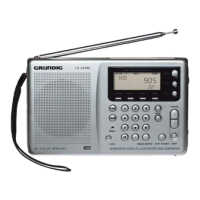
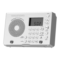
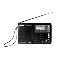
Description of front panel controls and their functions for R 1000 DPL.

Power Supply and AC Outlets

Details on power connection and AC outlet usage.

Operating Hints

Installation V 1000 DPL

Guide for setting up the V 1000 DPL unit.

Operating Elements V 1000 DPL

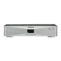
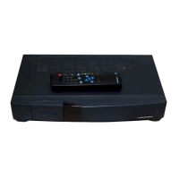
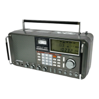
Description of front panel controls and their functions for V 1000 DPL.

Remote Control

Basic Operation and Battery Replacement

Covers general controls, battery replacement, and basic functions.

Source and Sound Control

Managing audio sources, volume, tuning, and tone adjustments via remote.

Advanced Features and Compatibility

D.O.T., display control, and operation of other brands.

Tuner Operation

Surround Sound Modes

Details on Pro Logic, 3-channel, and stereo modes.

Tuning and Station Management

Automatic/manual tuning, RDS, station memory, and naming.

Tuner Operation

Programme Type Selection

How to search for stations based on programme category.

Adjustment Procedures

Tuner Alignment

Alignment procedures for the tuner section.

Amplifier Alignment

Alignment procedures for the amplifier section.

Adjustment Procedures

Tuner Alignment Details

Detailed steps for tuning circuit alignment.

Amplifier Alignment Details

Detailed steps for amplifier quiescent current adjustment.

Alignment Layouts

Tuner Alignment Diagrams

Diagrams showing tuner alignment points and components.

Amplifier Alignment Diagrams

Diagrams showing amplifier alignment points and components.

Circuit Diagrams and PCB Layouts

R 1000 DPL Diagrams and Layouts

Wiring diagrams and PCB layouts for the R 1000 DPL.

V 1000 DPL Diagrams and Layouts

Wiring diagrams and PCB layouts for the V 1000 DPL.

DPL Logic Diagrams

DPL Logic Block Diagram

Block diagram illustrating the DPL logic circuitry.

Exploded Views

R 1000 DPL Exploded View Diagram

Exploded view illustrating the assembly of the R 1000 DPL.

Spare Parts Lists

R 1000 DPL Spare Parts List

List of spare parts for the R 1000 DPL with part numbers.

Exploded Views

V 1000 DPL Exploded View Diagram

Exploded view illustrating the assembly of the V 1000 DPL.

Spare Parts Lists

V 1000 DPL Spare Parts List

List of spare parts for the V 1000 DPL with part numbers.

Related product manuals