4. Installation
PNEG-2381 2000 Series U-Trough Bin Sweep Auger Unload System (72' - 78') 39
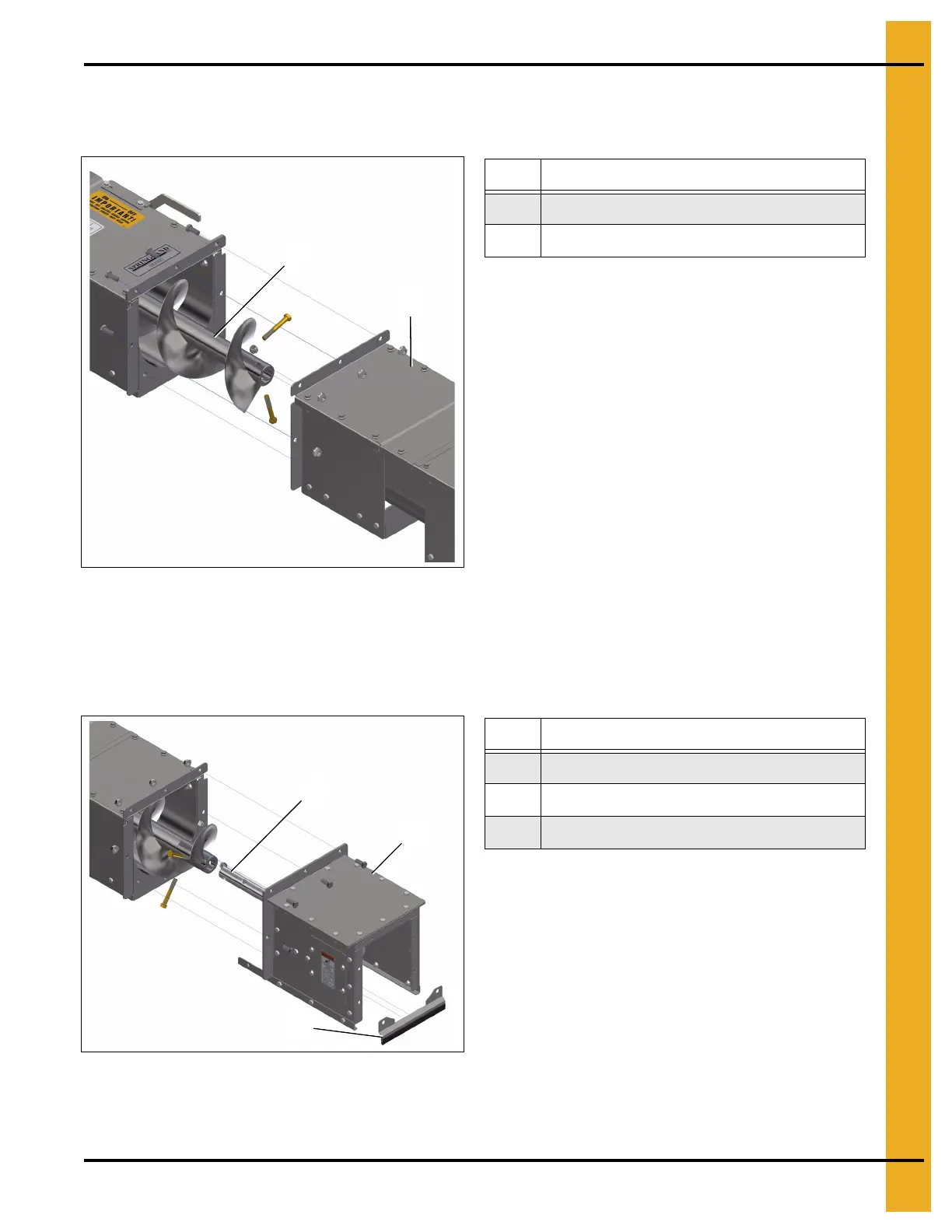
4. Install the UT extension (50) on the UT unloader box flange. Couple the extension flighting to the
unloader flighting (49) with the two 3-1/2" bolts removed in Step 2 on Page 38. Secure the extension
by installing the eight nuts and bolts removed in Step 3 on Page 38.
Figure 4BB
5. Re-install the powerhead (67). Install the powerhead shaft (76) on the extension flighting using the
two 3-1/2" bolts pre-installed on the extension flighting coupler. Re-install the discharge gate seal
(81). Secure the powerhead (67) to the extension with the bolts removed in Step 2 on Page 38.
NOTE: You can now proceed with typical powerhead installation as shown on Page 31.
Figure 4BC
6. Install the supports for extension (not included).
Ref # Description
49 Unloader Flighting
50 UT Extension
Ref # Description
67 Powerhead
76 Powerhead Shaft
81 Discharge Gate Seal
 Loading...


