4. Installation
PNEG-2381 2000 Series U-Trough Bin Sweep Auger Unload System (72' - 78') 35
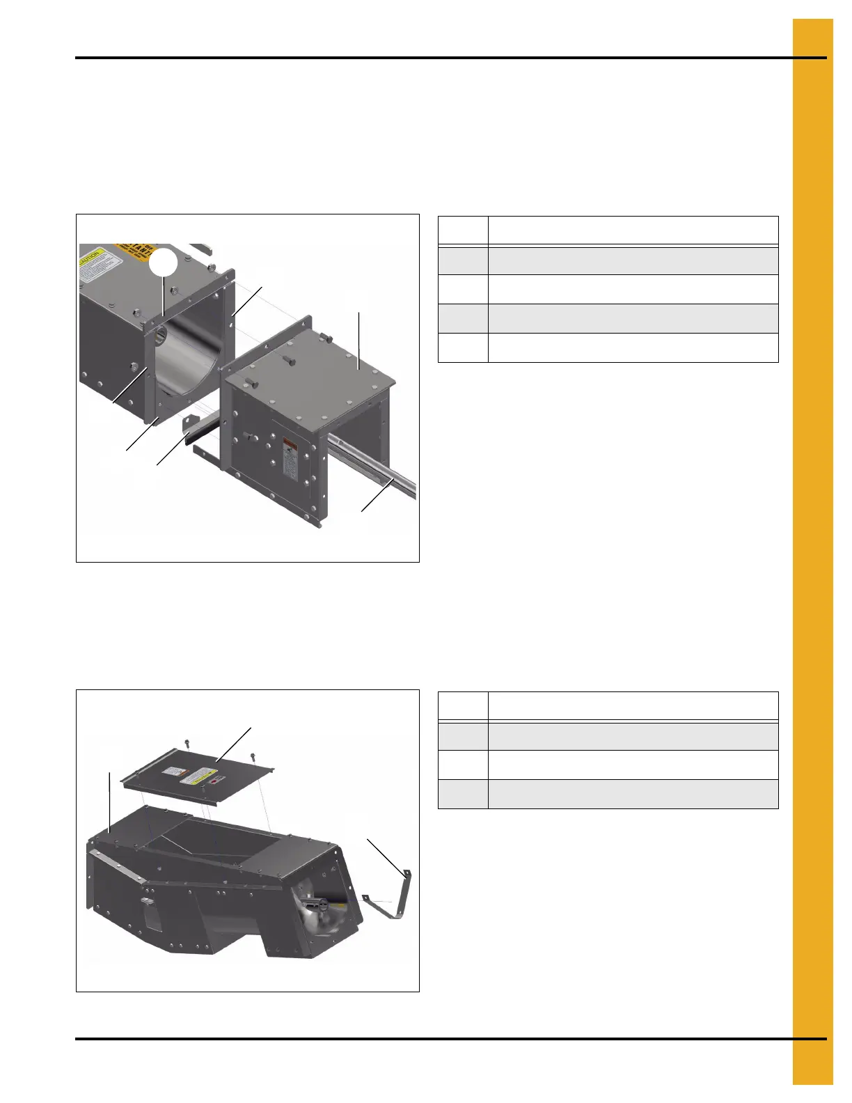
Incline Powerhead
1. Remove the powerhead (67) from the standard horizontal position by removing the eight bolts around
the perimeter of the box flange (80). Remove the discharge gate seal (81). The bolts securing the
discharge gate seal (81) are longer than other bolts securing the box flange (80). Keep them with the
discharge gate seal (81). Remove the powerhead shaft (76) from the unloader flighting by removing
two 3-1/2" bolts. (See Figure 4AQ.)
Figure 4AQ
2. Prepare the incline elbow assembly (84) for installation by removing the middle lid (83). Remove
four bin bolts and nuts. Remove the flight strap (82) securing the flighting by removing two flange
nuts and by removing the 3-1/2" bolt and nut in the flight bushing. The removed flange nuts can
be discarded. (See Figure 4AR.)
Figure 4AR
Ref # Description
67 Powerhead
76 Powerhead Shaft
80 Box Flange Perimeter
81 Discharge Gate Seal
Ref # Description
82 Flight Strap
83 Middle Lid
84 Incline Elbow Assembly
 Loading...


