www.gsl-energy.com - 7 -
Chart 2: Battery Capacity
Status Charging Discharging
Capacity LED Indicator
L4
L3 L2 L1 L4 L3 L2 L1
Capacity
0~25% OFF
OFF OFF Flash OFF OFF OFF NO
25~50% OFF
OFF Flash ON OFF OFF
NO
NO
50~75% OFF
Flash ON ON OFF
NO
NO
NO
75~100% Flash
ON ON ON
NO
NO
NO
NO
RUN Status NO Flash
3.4.Connectors
Charge / Discharge connectors: to connect the positive pole (+) and negative pole (-) from the battery
to the inverter via DC isolator.
Canbus/ RS485: Active communication portal between battery and inverter.
USB To RS232: to get dynamic monitoring data of the battery from upper computer.
Address: Reserved Address portal for multiple parallel connections.
3.5.Wake Up button
Battery On: When battery is shut down, press this RST button for 3 seconds. It is activated
when the LED lights flicker from RUN light to the lowest capacity indicator.
Battery off: When battery is activated, press this button for 3 seconds. It will be shut down
when the LED lights flicker from lowest capacity indicator to RUN light.
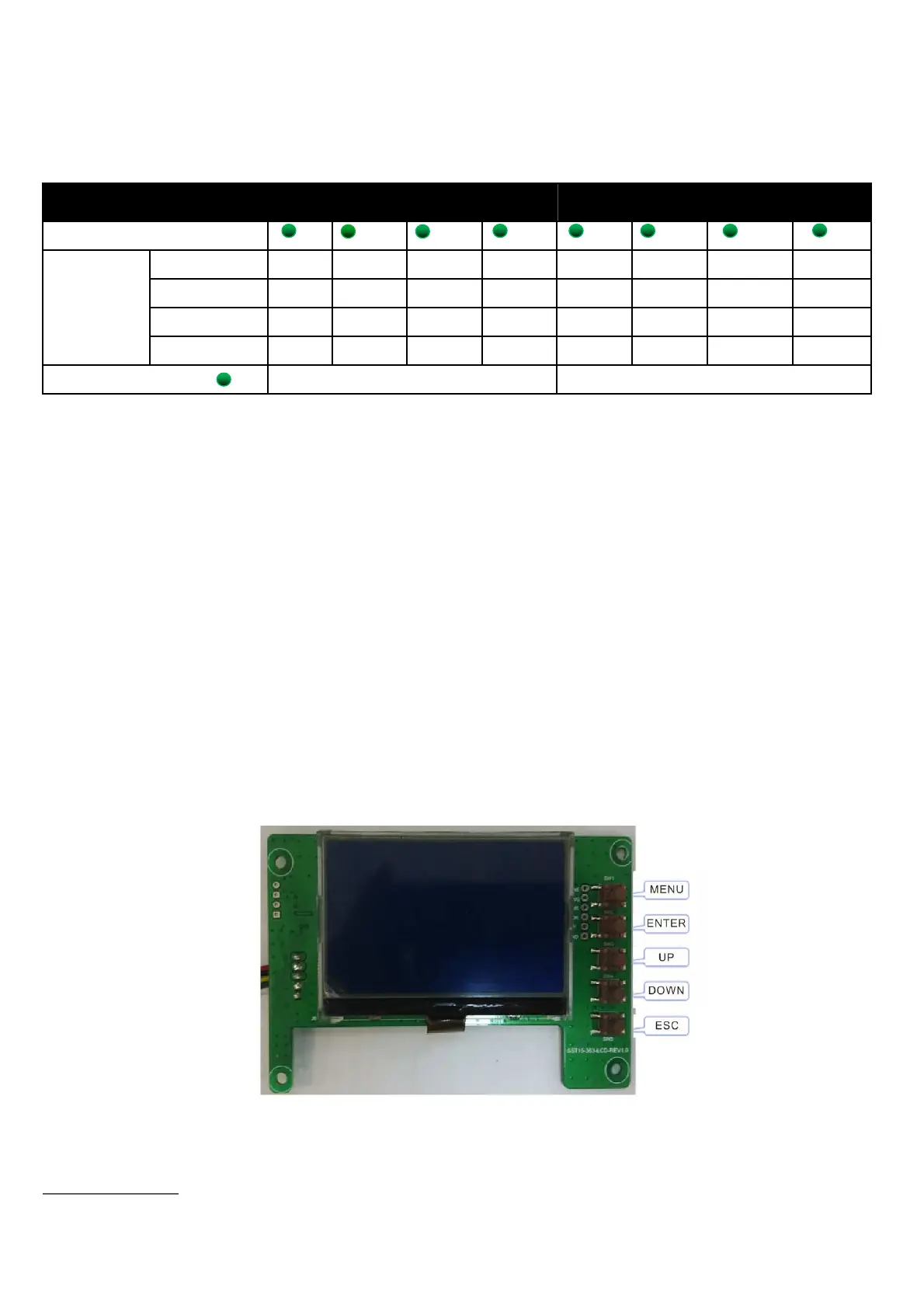
3.6.Display function instruction
3.6.1.Reference of real figure
 Loading...