Page 9
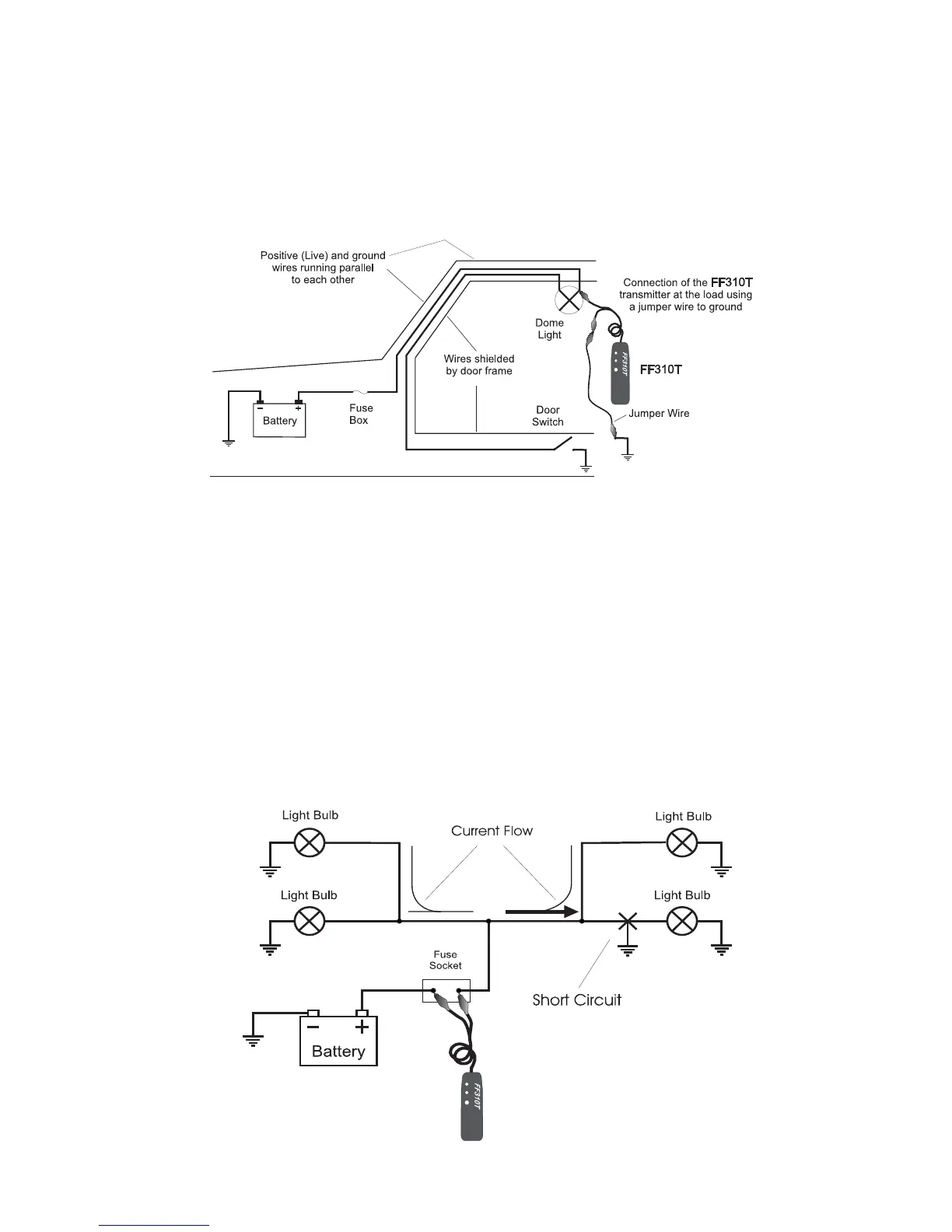
Fig. 9 - Simplified dome light circuit hook up for wire tracing
•
The spreading the circuit is achieved by connecting a jumper wire between the
live wire (preferably at a termination point in the circuit such as a light bulb socket,
switch, etc.), and a ground point somewhere else in the vehicle ( see Fig. 9). This
last method should be used only as “last resource” and with the FF310R set to low
sensitivity, as it could make the pinpointing of the precise location more diffi cult due
to the much increased range.
•
Always verify that the FF310T is connected in series with the circuit being tested and
that its red indicator light is on, as this confi rms a proper connection and will limit the
amount of current fl owing in the circuit.
13.3 Circuits with multiple loads or branches
•
When tracing circuits connected to, or which are powering multiple loads and/or
branches (See Fig. 10), and when these circuits are active or live, the bulk of the
current injected into the circuit by the FF310T will be directed to the shorted branch
of the circuit. However smaller amounts of current (or stray currents) will fl ow to the
other branches as long these provide a path to ground (i.e. close the circuit).
•
These stray currents present in the non-shorted branches of the circuit, and
depending on the circuit confi guration and physical layout of the wires, could
be picked up by the FF310R, making the tracing procedures confusing, and
even misleading.
•
The simplest and most effective way to deal with these cases, is to disconnect or
remove all the loads from the circuit being traced (i.e. removing light bulbs in
example shown in Fig. 10).
Fig. 10 - Schematic of a single circuit with multiples loads