Page 10
14 - Technical specifi cations
FF310T -Transmitter
Voltage range: 6 to 42 volts DC.
Indicator: Flashing green LED indicator for power on or open circuits.
Flashing red LED indicator for short circuits.
Power source: 9 volt alkaline battery, Duracell MN1604 or equivalent.
Connector: Two 5 Amp. universal micro-clips with auto polarity and 18” long cable.
Battery life: Approximately 25 hours of use.
FF310R - Receiver
Sensitivity: 3 User selectable levels (Low, Medium and High)
Probe: Flexible 8” gooseneck insulated steel probe with sensor.
Indicator: Green LED indicator for Power On and Open Circuits. Red LED
indicator for short circuits. Audio signal for shorts and opens.
Variable fl ashing and modulated audible signal.
Power source: 9 volt alkaline battery. Duracell MN1604 or equivalent.
Battery life: Approximately 25 hours of use.
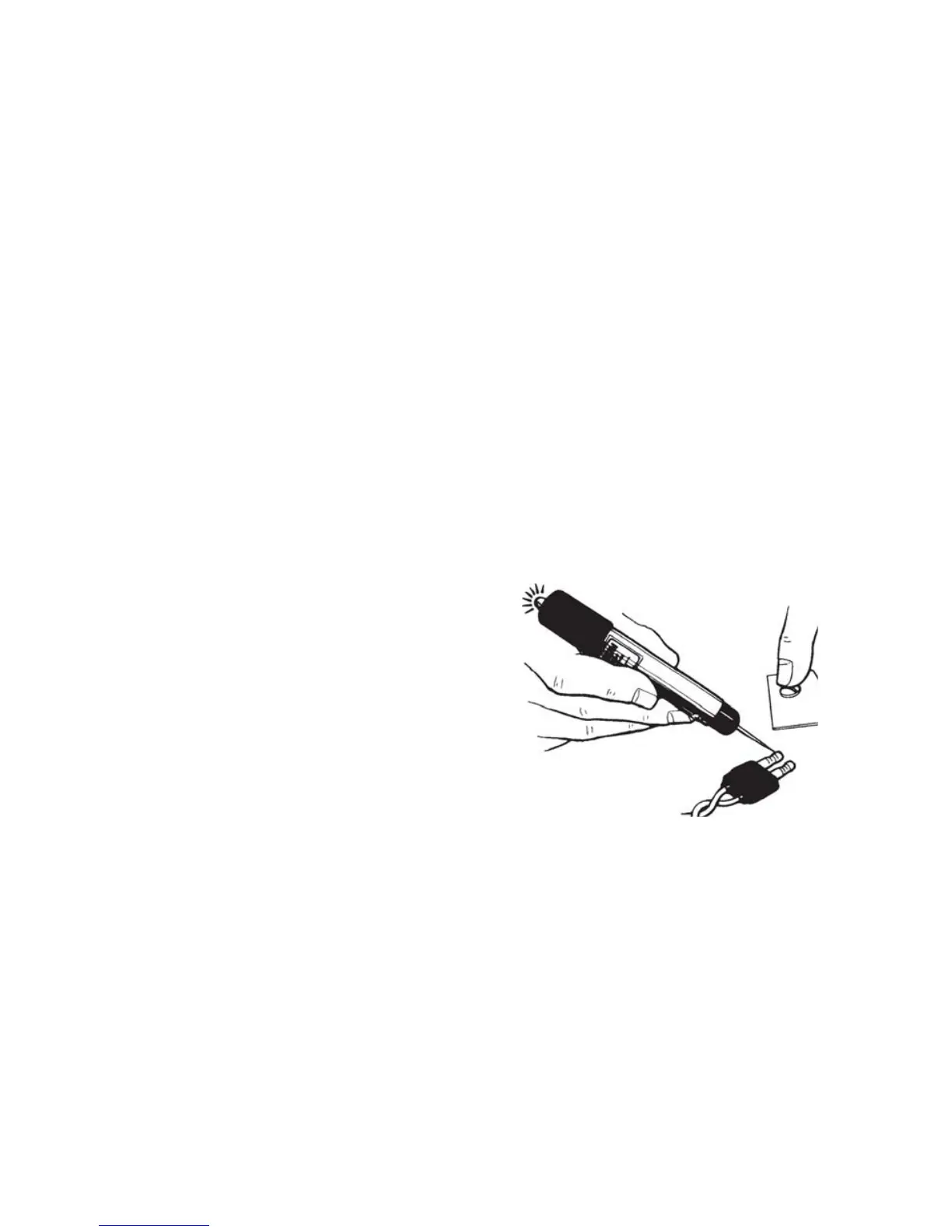
15 - CT8002AA Professional Circuit Tester
Instructions
1- Hold tester by metal barrel and place free
hand on bare (grounded) metal part of
the vehicle.
2- Place tester point into connector or wire
(pierce insulation if necessary).
3- Tester will emit a sound, vibrate, and the
red light turn on when a positive voltage is
detected.
V-Groove Protector Tip uses:
1- Always insert the V-Groove protector tip on the tester point before carrying or storing
the unit, as this may avoid injuries.
2- Use the V-Grove protector tip when piercing wires to prevent the tester point from
side-slipping on the wire and causing injuries or damage.
3- The protector tip may be removed for testing in hard to reach places inside connectors,
sockets, etc.
Replacing the battery:
The battery supplied with the tester will provide years of service under normal use. When the
sound, vibration, and light starts to fade, remove the screw and pull out the plastic pointer
assembly. Remove the battery and insert a new type IEC LR6 - ANSI/NEDA 15A (AA size
alkaline) or equivalent battery, observing the polarity (negative side goes in fi rst). Insert
the tester point assembly, then align the holes and replace the screw.