EasyManua.ls Logo

GTO E-Z GATE User Manual

GTO E-Z GATE
36 pages
To Next Page IconTo Next Page
Page #1 background imageLoading...
Page #1 background image
This product meets and exceeds the requirements of UL 325, the standard which regulates gate
opener safety, as established and made effective March 1, 2000, by Underwriters Laboratories Inc.
3121 Hartseld Road • Tallahassee, Florida, USA 32303
E-Z GATE/ Mighty Mule/GTO Sales: 1-800-543-GATE (4283) or (850) 575-0176 • Fax (850) 575-8912
or E-Z GATE/ Mighty Mule/GTO Technical Service: 1-800-543-1236 or (850) 575-4144 • Fax (850)575-8950
www.mightymule.com
rev-06.19.12
Printed in China for Gates That Open, LLC.
DUAL GATE OPENER
FM402
and
Installation Manual
®
WARNING!
This equipment is similar to other gate or door equipment and meets or exceeds
Underwriters Laboratory Standard 325 (UL 325). However, gate equipment has
hazards associated with its use and therefore by installing this product the installer
and user accept full responsibility for following and noting the installation and safety
instructions. Failure to follow installation and safety instructions can result in hazards
developing due to improper assembly. You agree to properly install this product and
that if you fail to do so Gates That Open, LLC, shall in no event be liable for direct,
indirect, incidental, special or consequential damages or loss of profits whether based
in contract tort or any other legal theory during the course of the warranty or at any
time thereafter. The installer and/or user agree to assume responsibility for all liability
and use of this product releasing Gates That Open, LLC, from any and all liability.
If you are not in agreement with this disclaimer or do not feel capable of properly
following all installation and safety instructions you may return this product for full
replacement value.
READ ALL INSTRUCTIONS CAREFULLY AND COMPLETELY before attempting to
install and use this automatic gate opener. This gate opener produces a high level of
force. Stay clear of the unit while it is operating and exercise caution at all times.
All automatic gate openers are intended for use on vehicular gates only.
Question and Answer IconNeed help?

Do you have a question about the GTO E-Z GATE and is the answer not in the manual?

GTO E-Z GATE Specifications

General IconGeneral
BrandGTO
ModelE-Z GATE
CategoryGate Opener
LanguageEnglish

Summary

Please Read This First

Important Safety Instructions

Consumer Safety and Pre-Installation

For The Consumer Safety Warnings

Critical safety warnings and precautions for users of automatic gates.

Installation Safety and Procedures

Safety During Installation

Guidelines for safe installation practices to prevent injury.

Post-Installation Safety

Essential steps and precautions after the gate opener is installed.

Gate Safety Precautions and Entrapment Protection

Required Safety Precautions for Gates

Mandatory safety measures for gate installation and use.

Entrapment Protection Measures

Explanation of safety devices to prevent entrapment.

Advanced Entrapment Protection

Secondary Entrapment Protection

Additional safety features for preventing entrapment.

Entrapment Alarm System

Details on the audio entrapment alarm and its function.

Warning Labels and Manual Operation

Warning Labels and Identification

Information on required warning signs and product identification labels.

Before You Begin: Charging Options

Determine Battery Charging Method

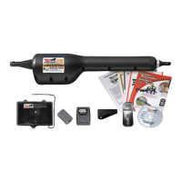
Choosing between transformer or solar panel for battery charging.

Installation of the FIRST Gate Opener

Install Post Bracket Assembly and Gate Bracket

Step 5: Position Opener for Clearance and Leverage

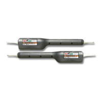
Ensuring proper clearance and leverage for opener mounting.

Step 6: Align Post Pivot Bracket and Check Clearance

Adjusting the post pivot bracket for smooth gate operation.

Attach Opener Arms

Step 1: Attach Opener Arms to Brackets

Connecting opener arms to post and gate brackets using pins and clips.

Step 2: Install Second Gate Opener

Installing the second opener following the same procedures.

Mount Battery Box and Control Box

Step 2: Mount Battery Box Securely

Mounting the battery box at least 3 feet above ground.

Connect Battery and Install Antenna

Step 4: Connect Battery Harness to Battery

Connecting red/black wires to positive/negative battery terminals.

Step 7: Attach Antenna to Control Box Cover

Securing the antenna to the control box cover.

Connect Power Cables and Transformer

Connect Transformer to Outlet

Connecting the transformer to the electrical outlet.

Step 5: Connect Low Voltage Wire to Terminals

Connecting transformer wires to the 14VAC OR SOLAR terminals.

Step 6: Connect Wire to Transformer Terminals

Connecting the low voltage wire to the transformer terminals.

Step 7: Plug Transformer into Outlet

Plugging in the transformer and recommending surge protection.

Set Closed Position Limit

Step 2: Set Second Gate Closed Limit

Using JOG buttons to set the closed position for the second gate.

Step 3: Set First Gate Closed Limit

Using JOG buttons to set the closed position for the first gate.

Step 4: Save Closed Position Limits

Pressing SET LIMIT to save the closed position settings.

Step 5: Test Open Position Limits

Pressing remote to open gates and verify open limits.

Step 6: Verify Closed Position Accuracy

Re-pressing remote to confirm gates close correctly.

Adjust Stall Force Setting

Personalize Remote Setting

Step 2: Set Remote DIP Switches

Configuring the remote's unique code using DIP switches.

Step 3: Program Remote to Control Board

Synchronizing the remote with the gate opener control board.

Push-To-Open Installation Instructions

Step 2: Determine Mounting Position

Positioning post brackets for push-to-open gates.

Solar Panel Instructions

Connecting Accessories and Safety Devices

Accessory Inputs Explained

Troubleshooting Guide

Warranty Repair

Related product manuals