Do you have a question about the GTO 3000XLS and is the answer not in the manual?
Details hazards, installer responsibility, and user liability for improper installation and use.
Emphasizes reading all instructions for safe operation and caution during use.
Confirms product meets UL 325 standards for gate operator safety.
Defines categories for residential, commercial, industrial, and restricted access vehicular gate operators.
Provides tables for converting metric to English units and vice versa, plus temperature conversions.
Section to record serial number, place, and date of purchase for service and assistance.
Details gate length, weight limits, and suitable gate materials for the operators.
Lists compatible optional accessories like transmitters, keypads, and locks.
Explains the adjustable stall force safety feature and the auto-close function.
Provides contact numbers for information about GTO/ACCESS SYSTEMS products and dealers.
Highlights potential hazards associated with automated gate systems and installer responsibility.
Explains the meaning of the warning symbol used to denote potential serious injury or death.
Details the procedure for manually opening and closing the gate when the operator is disconnected.
Step-by-step guide on how to disconnect the gate operator from its mounting points.
Critical warnings for consumers on reducing injury/death risk, including placement and clearance.
Ensures operator suitability, gate condition, familiarity with features, and proper use.
Diagram and explanation of entrapment zones for pull-to-open gate installations.
Guidelines for safe installation practices, avoiding pinch points and securing controls.
Instructions for attaching warning signs, gate maintenance, and keeping children/pets away.
Emphasizes knowing how to disconnect the operator for manual gate operation.
Mandates warning signs and recommends pedestrian gates and entrapment protection devices.
Recommends safety edge sensors or photo beams for enhanced entrapment protection.
Explains UL 325 requirements for inherent and secondary entrapment sensing systems.
Guidance on placement and use of photo-electric sensors (Type B1) for entrapment protection.
Guidance on placement and wiring of safety edge sensors (Type B2).
Describes the audio entrapment alarm that activates after two obstructions within a cycle.
Displays and explains critical warning labels regarding moving gate dangers.
Details UL 325 compliance and physical limitations for gate operators.
Concise instructions for manually opening and closing the gate.
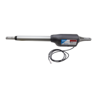
Details the linear actuator, motor, speed, and opening arc of the gate operator.
Specifies the 12V battery, transformer, and fuse ratings for the system.
Describes DIP switches, auto-memorization, RF receiver, and safety sensor compatibility.
Provides gate capacity chart based on length and weight, and notes on hinge requirements.
Guidance on choosing between transformer or solar power for battery charging.
Critical warning against using transformer and solar panels simultaneously to prevent damage.
Illustrates expected daily gate cycles based on solar panel wattage and geographic zone.
Notes that connected accessories draw extra power from the battery.
Confirms the system is designed for pull-to-open gates and notes push-to-open bracket requirement.
Ensures gates are plumb, level, swing freely, and posts are secured for installation.
Details the gate grounding kit and procedure to reduce risk from lightning strikes.
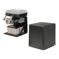
Lists components like the control box, receiver, transmitter, and transformer.
Lists components for the bracket box: post bracket, gate bracket, pivot bracket, and stop plates.
Details the various bolts, washers, nuts, clevis pins, and bushings included in the hardware bag.
Identifies the main 3200XLS operator unit.
Lists components for the bracket box: post bracket, gate bracket, pivot bracket, and stop plates.
Details the various bolts, washers, nuts, clevis pins, and bushings included in the hardware bag.
Lists necessary tools for installation, including drill, wrenches, screwdrivers, and clamps.
Specifies 16 gauge stranded wire for transformer, solar panel, and accessories.
Recommends a 10-watt solar panel for gates over 1000 ft. from AC power.
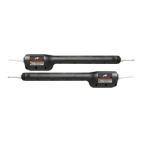
Defines the 3000XLS as MASTER and 3200XLS as SECOND based on control box location.
Illustrates a pull-to-open dual gate installation with key components and placement.
Provides steps for installing the 3000XLS master gate operator.
Details mounting the post bracket on a flat post, including material considerations.
Describes using a level to scribe a line for determining bracket position.
Details positioning the post bracket and marking holes for drilling.
Instructions for drilling holes and securely mounting the post bracket with hardware.
Explains how to attach the post pivot bracket to the post bracket.
Details connecting the operator's rear mount to the post pivot bracket.
Explains attaching the gate bracket to the operator's front mount.
Checks for minimum 2" clearance between operator arm and gate in open/closed positions.
Checks for minimum 2" clearance between operator arm and gate in open/closed positions.
Checks operator for binding at the post pivot bracket in the closed position.
Details drilling holes in the gate and attaching the gate bracket.
Details drilling holes in the gate and attaching the gate bracket.
Connects the operator arm to the post bracket and gate bracket using pins and clips.
Connects the operator arm to the post bracket and gate bracket using pins and clips.
Instructs to follow steps 1-10 on pages 8-10 for installing the second operator.
Details the installation of positive stops to secure gates in the closed position.
Explains that positive stops stabilize gate leaves in the closed position for security.
Details attaching horizontal stop plates to the gate frames for the closed position.
Notes the requirement for a ground stop post when using the automatic gate lock.
Instructs on installing a low profile ground stop beneath the second gate stop plate.
Details attaching a vertical stop plate to the second gate frame to meet the ground stop.
Instructs to return gates to open position and reattach gate operators.
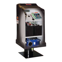
Details mounting the control box at least 3 feet above ground and from AC power sources.
Advises temporary mounting of the receiver for range testing before permanent installation.
Lists factors for optimal receiver placement: line-of-sight, distance from AC, height, and surface.
Provides guidelines on receiver cable length, splicing, conduit use, and AC wiring proximity.
Describes cutting a slot for conduit to protect the second operator's power cable.
Details feeding power cables through strain reliefs into the control box.
Instructions for connecting the master operator's power cable to the control board.
Instructs on connecting stripped power cable wires to MASTER OPERATOR terminals.
Instructions for connecting the second operator's power cable to the control board.
Instructs on connecting stripped power cable wires to SECOND OPERATOR terminals.
Details transformer use, wire type, splicing, and simultaneous use of transformer/solar.
Instruction to turn the control box power switch OFF before connecting power input.
Guides on selecting the electrical outlet and measuring distance for wire layout.
Details laying low voltage wire in a trench and protecting it with conduit.
Instructs on feeding low voltage wires through the strain relief into the control box.
Details stripping and connecting low voltage wire to the 18 VAC or SOLAR terminals.
Explains stripping and attaching transformer wires to the transformer terminals.
Ensures the control box power switch is OFF before connecting the battery.
Crucial instruction to connect black wire to NEGATIVE and red wire to POSITIVE terminals.
Instructs to plug the transformer into the electrical outlet, recommending a surge protector.
Guides on setting the closed position limit for pull-to-open gate applications.
Details programming the closed limit for master or second gate.
Instructs to press transmitter to open gates for programming.
Instructs to press transmitter to close gates for programming.
Details stopping the second gate to set its closed limit.
Instructs to press transmitter to open gates and finalize programming.
Explains stall force sensitivity and how to adjust the potentiometer.
Explains stall force sensitivity and how to adjust the potentiometer.
Details how the Auto-Close Time potentiometer determines gate open duration before closing.
Details how the Auto-Close Time potentiometer determines gate open duration before closing.
Recommends changing factory settings for safety and security. Lists compatible transmitters.
Instructions for removing the transmitter cover using a Phillips head screwdriver.
Guides on setting the nine transmitter DIP switches according to safety and security needs.
Details pressing transmitter button and LEARN RMT button to store new code.
Emphasizes testing receiver range before permanently installing the transmitter.
Configures soft start/stop feature for smoother gate operation and reduced wear.
Enables or disables the warning buzzer for gate movement and obstructions.
Sets the operator for push-to-open or pull-to-open gate configurations.
Determines if the second gate opens simultaneously with or after the master gate.
All control inputs are dry-contact, normally open, and connected to COMMON terminal.
Defines the circuit common terminal for all logic inputs.
Controls gate operation (open-stop-close-stop-open) with activation.
Activates safety features, stopping or preventing gate movement based on input.
Opens the gate or restarts auto-close timer when activated.
Monitored only when gate is fully open; prevents closing.
Stops and reverses gate when closing if an obstruction is detected.
Stops and reverses gate when opening if an obstruction is detected.
Illustrates connection for an automatic gate lock accessory.
Shows wiring for a push button control for simple open/close/stop operation.
Illustrates the connection for a digital keypad for property access.
Shows wiring for an edge sensor (safety device).
Illustrates connection for photo beams as a non-contact entrapment protection.
Refers to manual for connecting a vehicle sensor for additional connections.
Provides connection details for sirens, lights, and other auxiliary devices.
Describes the dry-contact relay output for sirens, lights, etc., with rating and behavior.
Warns that swinging gates must not open into public access areas.
Explains that push-to-open gates extend outward and require a specific bracket.
Provides steps for installing the operator for push-to-open configurations.
Instructs to follow general 3000XLS installation steps from page 7.
Highlights differences: arm extends to open, retracts to close.
Operator is installed while the gate is in the CLOSED POSITION (arm retracted).
Mandates the use of the Push-to-Open Post Pivot Bracket [R4388].
Emphasizes 2" clearance for efficient leverage and minimal pinch area.
Instructs to install the second operator in the same manner as the first.
Ensures control box power is OFF before changing DIP switch settings.
Instructs to move DIP Switch 3 from OFF (Pull-To-Open) to ON (Push-To-Open).
Ensures power is on and gates are in the CLOSED position for limit setting.
Instructs to press transmitter to activate operator arms to open the gates.
Details stopping the master or second gate at its open position.
Instructs to press transmitter to close gates, programming the current position.
Instructs to press transmitter to activate arms and open gates.
Details stopping the second gate at its open position to set the limit.
Instructs to press transmitter to close gates, finalizing open limit programming.
Provides guidance for installing operators on masonry, brick, or rock columns.
Suggests push-to-open configuration for easier clearance on columns.
Recommends re-hanging the gate on a post or moving it to the back corner.
Describes cutting a notch in the column as a difficult solution for experienced users.
Diagnoses normal operation or issues with fuse, battery, or connections.
Diagnoses fuse, battery, or connection issues causing beeps on activation.
Indicates obstruction detection, gate level issues, stall force, or safety devices.
Indicates low battery condition, checked via fuses or battery harness.
Points to master motor terminal short or circuit board issues.
Indicates second motor terminal short or circuit board issues.
Suggests master arm limit switch error or power cable issues.
Indicates second arm limit switch error or power cable issues.
Points to master arm rev counter error or power cable issues.
Suggests second arm rev counter error or power cable issues.
Indicates cycle terminal short; suggests disconnecting accessories.
Indicates safety terminal short; suggests disconnecting accessories.
Indicates exit terminal short; suggests disconnecting accessories.
Indicates shadow terminal short; suggests disconnecting accessories.
Indicates close edge terminal short; suggests disconnecting accessories.
Indicates open edge terminal short; suggests disconnecting accessories.
Indicates normal operation with remote/keypad or RF signal issues.
Indicates no 318 MHz RF received; checks battery, remote programming, or antenna.
Indicates AC or solar power is present for normal operation.
Provides expected voltage readings for transformer, solar panel, battery, and charging circuit.
Recommends first using the troubleshooting guide before contacting service.
Advises using the online troubleshooting wizard for assistance.
Provides contact numbers and required information for service calls.
Details assigning an RGA number for necessary repairs or replacements.
Instructions for securely packing and shipping equipment with RGA number.
Specifies that products without RGA or returned freight collect will not be accepted.
Details accessories related to powering the gate operator system.
Describes the 16 gauge dual conductor wire for connecting components.
Details solar panel kits for maintaining battery charge when AC power is distant.
Provides additional battery power or serves as a replacement for the existing battery.
Lists accessories for controlling vehicle access and exit.
Lists single, dual, and three-button transmitters for operating gate operators.
Allows one remote to activate gate operator and garage door opener.
Enables property access via identification codes, programmable up to 25 codes.
Provides secure gate entrances and controlled access with audio/visual features.
Designed for mounting keypads, intercoms, and other access control devices.
Accessories for automatic gate activation based on vehicle presence.
Activates gate operator hands-free when a vehicle exits property.
Automatically activates gate operator hands-free when a vehicle exits.
Accessories designed to enhance gate security and stability.
Locks and unlocks automatically for security, ideal for high wind conditions.
Secures horizontal pedestrian gates, ideal for pools and schools.
Alerts of vehicles entering driveway with a chime signal.
Lists various additional accessories for gate operation and safety.
Provides primary 'through beam' photo beam for non-contact entrapment protection.
Used as a substitute for clevis pin to prevent operator theft.
Wired for simple open/close/stop operation up to 1000 ft. away.
Standard 18 volt, 2200 mA AC transformer for maintaining battery charge.
Reduces risk of electronic equipment damage from lightning strikes.
Details hardware components and brackets for installation.
Required for push-to-open gates; order two for dual swing gates.
Used with automatic or pedestrian gate locks for brick columns or limited space.
| Gate Type | Swing |
|---|---|
| Type | Gate Opener |
| Safety Features | Auto-reverse, Obstruction detection |
| Remote Control | Yes |
| Battery Backup | Optional |
| Warranty | 1 year |