16 GTO 3000XLS/3200XLS Instruction Manual © 01.10.12
IMPORTANT:
• Thetransformerisdesignedandintendedforindooruse.Ifthetransformercanonlybe
plugged into an outside electrical outlet, a weatherproof cover/housing (available at local
electrical supply stores) must be used.
• TheonlywireacceptableforusewithGTOproductsis16gaugestranded,lowvoltage,direct
burial wire
[RB509]. This particular gauge enables the transformer to provide an adequate
charge through the control board to the battery at distances up to 1000 ft.
• DONOTusetelephonewireorsolidwire.
• NEVERsplicewires.Splicingpermitscorrosionandseriouslydegradesthewire’sabilitytocarry
an adequate current.
• NEVER USE TRANSFORMER AND SOLAR PANEL(S) AT THE SAME TIME! Doing so will
damage the control board.
• Ifyourgateismorethan1000ft.fromanACpowersource,youwillneedtouseatleast10
watts solar charging power
[FM122/FM123] to charge the battery. Refer to the Solar Panels
and Gate Activity Chart on page 2.
Step 1
Make sure the control box power switch is OFF.
Step 2
Select the electrical outlet outlet into which you will plug the transformer. Measure the distance from this
outlet to the control box following the path where the wire will be laid (allow for an additional 6” to be
pulled into the control box).
Step 3
Lay the low voltage wire in a trench following a path from the
selected electrical outlet to the control box. Wires coming up
from the ground should be run through PVC conduit to protect
them from lawn mower blades, weed eaters, and grazing
animals. Bury the wire in the trench.
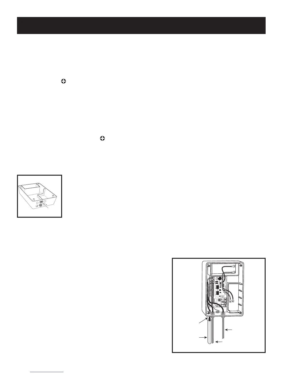
Step 4
Feed the low voltage wires upward through the strain relief
opening on the lower left of the control box. Pull 6” to 8” of wire
into the control box.
Low Voltage Wire
from Transformer
Power Cable from
Master Operator
Power Cable from
Secondary Operator
PVC Pipe
25
FUSE
BATT +
BATT -
1 2 3 4
ON DIP
STATUS
LEARN RMT
RECEIVER
LEARN
MAST LIMIT
LEARN
SLV LIMIT
S3
S4
ALM
S2
OFF
SOFT START OFF
WARNING OFF
OPEN PULL
SLV OPEN DLY.
MODE1 OFF
MODE2 OFF
ON
ON
PUSH
SIMULT.
ON
ON
120 MIN MAX
CHARGING
PWR IN
GTO RCVR.
WHT
BLU
BRN
ORG
RED
BLK
GRN
WHT
BLU
BRN
ORG
RED
BLK
GRN
COM
GRN
BLK
RED
CYCLE
SAFETY
EXIT
SHADOW
OPEN
EDGE
COM
GTO
TRANSF
LOCK
PWR
AUX
RLY
POWER
INPUTS
CONTROL
OUTPUTS
MASTER CABLESECOND CABLE
CONTROL INPUTS
AUTO CLOSE TIME STALL FORCE
CLOSE
EDGE
18 VAC
or
SOLAR
GTO
LOCK
AUX
Connect the Power Input
ON/OFF Switch