14 GTO 3000XLS/3200XLS Instruction Manual © 01.10.12
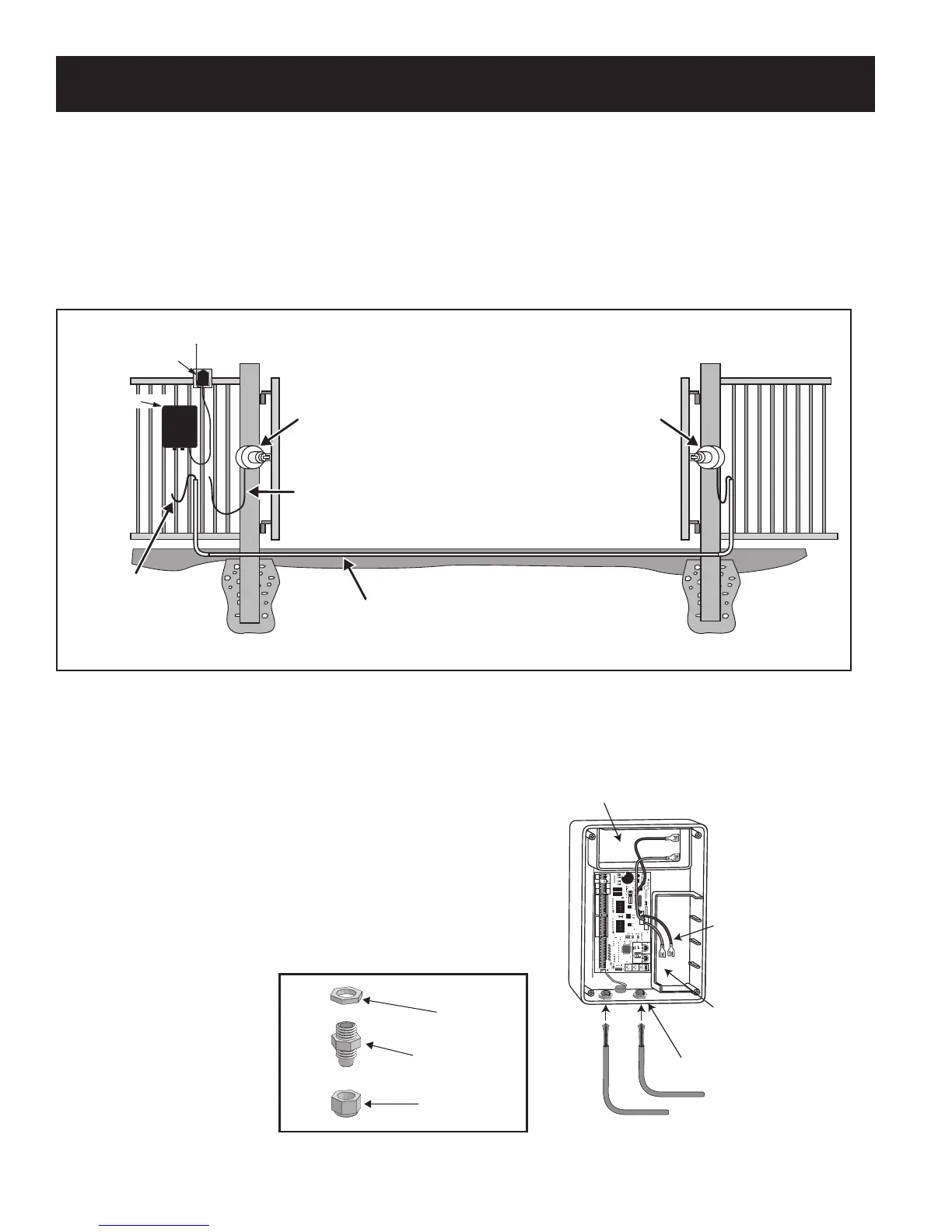
Connect Operator Power Cables
Step 2
Loosen sealing nuts on strain relief hubs at bottom of control
box. Insert power cables into control box through strain
reliefs. Thread approximately 6” to 8” of the power cables into
the control box and retighten sealing nuts until the power
cables lock into place.
Master Operator Power Cable
Secondary Operator Power Cable
Strain Relief
Battery wires for
optional second battery.
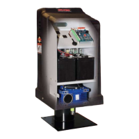
Space for optional
second 12 Volt battery
(see Accessory Catalog)
Space for 12 Volt
battery (included).
25
FUSE
BATT +
BATT -
1 2 3 4
ON DIP
STATUS
LEARN RMT
RECEIVER
LEARN
MAST LIMIT
LEARN
SLV LIMIT
S3
S4
ALM
S2
OFF
SOFT START OFF
WARNING OFF
OPEN PULL
SLV OPEN DLY.
MODE1 OFF
MODE2 OFF
ON
ON
PUSH
SIMULT.
ON
ON
120 MIN MAX
CHARGING
PWR IN
GTO RCVR.
WHT
BLU
BRN
ORG
RED
BLK
GRN
WHT
BLU
BRN
ORG
RED
BLK
GRN
COM
GRN
BLK
RED
CYCLE
SAFETY
EXIT
SHADOW
OPEN
EDGE
COM
GTO
TRANSF
LOCK
PWR
AUX
RLY
POWER
INPUTS
CONTROL
OUTPUTS
MASTER CABLESLAVE CABLE
CONTROL INPUTS
AUTO CLOSE TIME STALL FORCE
CLOSE
EDGE
18 VAC
or
SOLAR
GTO
LOCK
AUX
Sealing Nut
Hub
Lock Nut
Strain Relief
Step 1
Review the Installation Overview illustration below before proceeding.
Cut a slot into the driveway to accommodate 3/4” PVC conduit (not provided). The buried conduit will
protect the SECOND operator power cable from automobile tires, lawn mower blades, weed eaters, and
grazing animals. Pull the SECOND operator power cable through the conduit, up to the Control Box.
Receiver
PVC conduit (not included)
to protect SECOND operator
power cable from lawn mowers
and weed eaters.
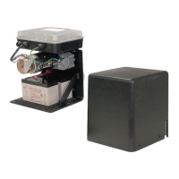
Control Box
Power Cable
from SECOND
Gate Operator
GATES IN THE OPEN POSITION
WITH OPERATORS INSTALLED
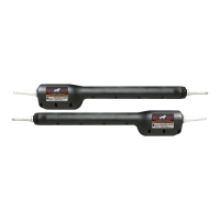
MASTER Gate Operator
Power Cable
from MASTER
Gate Operator
SECOND Gate Operator

 Loading...