EasyManua.ls Logo

GTO Automatic Gate Lock User Manual

GTO Automatic Gate Lock
8 pages
To Next Page IconTo Next Page
Page #1 background imageLoading...
Page #1 background image
1
PLEASE NOTE: Because of the various mounting applications, no mounting hardware is
provided with the GTO Automatic Gate Lock. All necessary mounting hardware can be ob-
tained from your local hardware store; all other hardware is provided.
This manual shows two examples of the most common installations, and should provide insight
into most other applications. If you have any questions during installation, please call (850)
575-0176 for technical support.
Installation Manual
RB909 rev-05/18/01
© GTO, Inc. 2000
AUTOMATIC
GATE LOCK
®
IMPORTANT: Before you install the automatic gate lock be sure your gate is level, moves freely on its
hinges, and does not bind or drag against the ground.
Question and Answer IconNeed help?

Do you have a question about the GTO Automatic Gate Lock and is the answer not in the manual?

GTO Automatic Gate Lock Specifications

General IconGeneral
BrandGTO
ModelAutomatic Gate Lock
CategoryGate Opener
LanguageEnglish

Summary

Before You Start

Gate Opener Compatibility & Adjustments

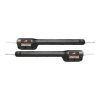
Discusses adjustments needed for Mighty Mule and GTO/PRO gate openers.

Push-to-Open Gate Considerations

Explains lock placement for push-to-open gates and potential post modifications.

Parts and Hardware Checklist

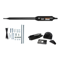
Lists all included parts and specifies required mounting hardware for different gate types.

Mounting The Lock

Disconnecting the Gate Opener

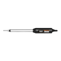
Detaches the gate opener to allow free gate movement during lock installation.

Positioning and Securing the Lock Receiver

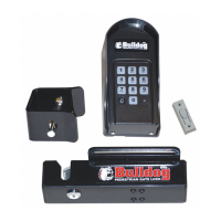
Determines the best level and aligned location for the receiver on the gate post and secures it.

Mounting and Aligning the Lock

Marks, drills, and secures the lock to the gate supports, then installs the clevis pin.

Manual Lock Release Procedure

Explains how to use the key for manual operation if electronic release fails.

Connecting the Control Boards

Preparation and Power Off

Turns off power, removes cover, and disconnects battery leads before wiring.

Lock Board Terminal Wiring

Connects lock board wires (WHITE, RED, BLACK) to specified terminals on the lock and control boards.

Using Scotch Loc Connectors

Attaches the WHITE wire and opener power wire using Scotch Loc connectors for specific gate directions.

Final Connections and System Testing

Reconnects opener, connects battery leads, powers on, and tests functionality.

Generation 2000 Control Boards Wiring

White Wire to Opener Terminal Connection

Connects the lock board's WHITE wire to the opener terminal block based on gate direction.

Battery Terminal Wire Connections

Details connecting the BLACK and RED wires from the lock board to the battery terminals.

GTO PRO 2000 Specifics and Warranty

GTO/PRO 2000 Wiring Procedure

Connects the WHITE wire to the OPENER terminal block and then to battery terminals.

Limited One Year Warranty Terms

Outlines the one-year limited warranty, repair/replacement policy, and exclusions.

GTO Service Department Contact

Provides GTO Service Department phone numbers for questions, assistance, and returns.

Related product manuals