4 F320 Instruction Manual
rev 03.26.13
To avoid damage to the unit from static discharges, connect
the EARTH GROUND terminal to a good earth grounding
point. Suggested wiring size is 18 AWG for earth ground
and power (up to 500 feet of 18 AWG wire can be run for
power, use larger wire for longer runs). Use 22 AWG or larger
(depending on the load) for all other connections.
CAUTION: If the unit is AC powered, and one side of
the power transformer secondary is connected to earth
ground, connect the grounded side to the “-” power
terminal of the unit.
Select a location for the keypad. For door access control
installations, mount the keypad near the controlled door.
For gate control installations, mount the keypad in clear
view of the gate, but far enough from the gate so the
user cannot touch the gate from the keypad.
WARNING: TO AVOID SERIOUS INJURY OR DEATH,
MAKE SURE THAT THE UNIT IS FAR ENOUGH FROM THE
GATE SO THAT THE USER CANNOT TOUCH THE GATE
WHILE OPERATING THE KEYPAD. HOWEVER, THE GATE
MUST BE FULLY VISIBLE FROM THE KEYPAD.
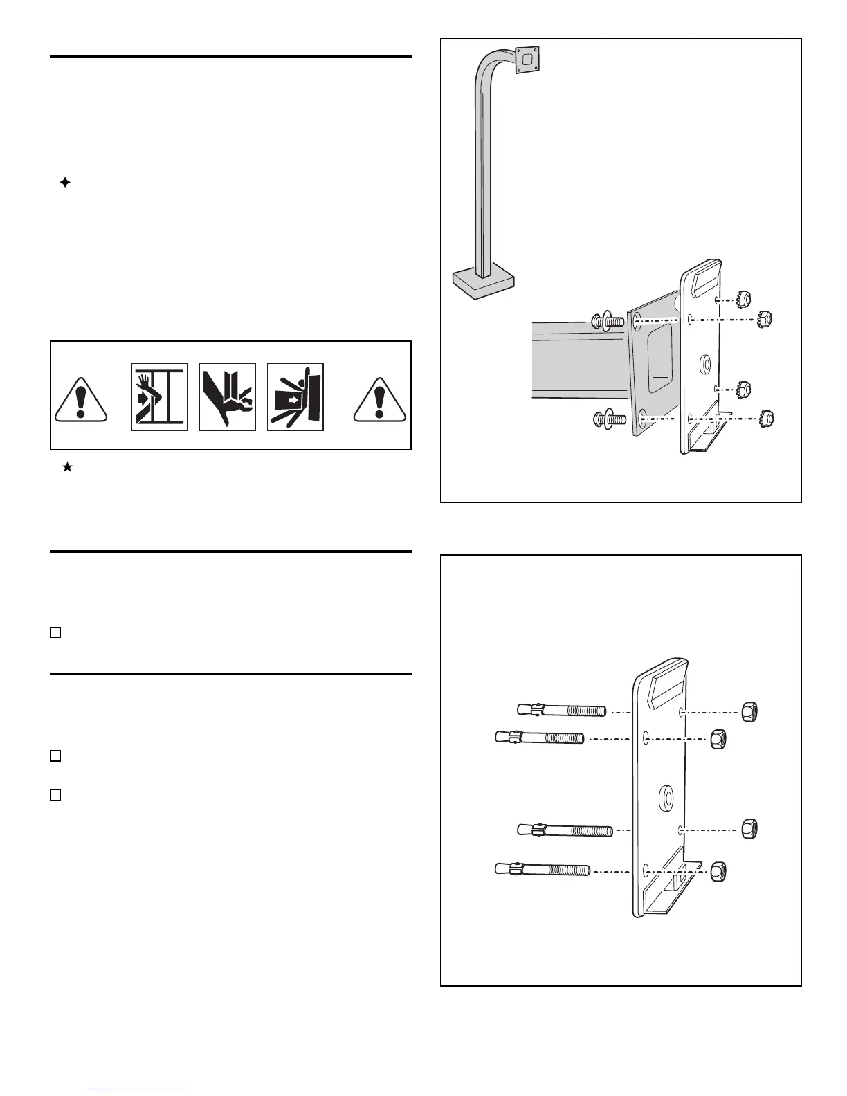
Pedestal Mounting
The F320 keypad can be mounted on a standard
pedestal.
Use four security bolts and locking nuts to secure the
keypad’s backplate to the pedestal (see Figure 3).
INSTALLATION
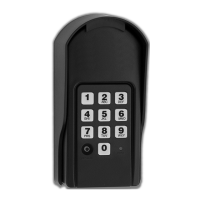
Wall Mounting
The F320 keypad can be mounted directly to a wall or
at surface.
Use the appropriate fasteners to secure the keypad’s
back plate to the mounting surface.
When mounting the keypad to a concrete wall,
use concrete wedge anchors or molly anchors (see
Figu re 4).
PEDESTAL
MOUNT BACKPLATE WITH
SECURITY BOLTS AND LOCKNUTS
Figure 3. Pedestal Mounting Keypad Backplate
USE CONCRETE
WEDGE ANCHORS
OR MOLLY ANCHORS
WALL MOUNTING
Figure 4. Wall Mounting Keypad Backplate