EasyManua.ls Logo

GTO R4211 - User Manual

GTO R4211
19 pages
Print Icon
To Next Page IconTo Next Page
Loading...
R4211
(PRO3040-G3)
Replacement/Upgrade Control Board for
MM500 • MM502
SW2000XL • SW2002XL
SW2500 • SW2502
SW3000 • SW3000XL
SW4000 • SW4000XL
R4211 ENHANCEMENTS
• Better Soft Stop/Start Functions
• Smoother Hookup
• Plug & Play just like 3040
• Easier to set limit for dual application, it has master & slave button and not dip switches
• Increased surge protection on accessory terminals
Auto Close potentiometer will set 3-120 seconds, not with dip switches as previous version
that only gave 4 options
• Improved Charging circuit will charge all the time; The battery will be charged in stages not
charge to full and then stop
The circuit board pulls 25 milliamps not 40 like the old board. It is better for solar applica-
tions
• Battery connectors are at the top and soldered on and not plug in like the 3040 board – we
used to have to suggest tightening previously
• Sequencing is automatically set for dual application. The slave will always close first.
3rd Generation Control Board, (Blue Board)
For Single or Dual Systems
Replaces PRO3040PCB, R4206, R4207, MM500PCB, MM502PCB
NOTICE
The Following GTO PDF Manual Pages
Apply to the Below Listed GTO Operators
Where you read the phrase “The GTO PRO® 3000...”;
It applies to all the below listed operators.
GTO’s PDF BEGINS ON NEXT PAGE
Question and Answer IconNeed help?

Do you have a question about the GTO R4211 and is the answer not in the manual?

Summary

Wiring and Programming Instructions

Connecting Opener Power Cable

Step-by-step guide for connecting the gate opener power cable to the control board.

Powering the System

Control Board Settings

DIP Switch Configuration

How to set DIP switches for various functions like Soft Start and Buzzer.

Setting Closed Position Limit

Programming the desired closed position for pull-to-open applications.

Obstruction Sensitivity Adjustment

Setting the stall force for gate obstruction detection sensitivity.

Connecting Safety Devices

Maintenance and Troubleshooting

LED Indicators on Non-Working Opener

Diagnosing issues using LED error codes for a non-functional opener.

Overview

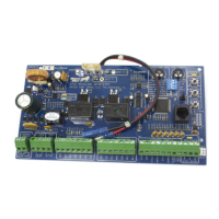
The GTO PRO® 3040-G3, also known as the R4211, is a 3rd Generation Control Board (Blue Board) designed for single or dual gate opener systems. It serves as a replacement or upgrade for several GTO models, including PRO3040PCB, R4206, R4207, MM500PCB, MM502PCB, MM500, MM502, SW2000XL, SW2002XL, SW2500, SW2502, SW3000, SW3000XL, SW4000, and SW4000XL.

Function Description:

The R4211 control board manages the operation of automatic gate openers, providing features for opening, closing, safety, and accessory integration. It is designed to enhance the performance and reliability of GTO gate systems.

Important Technical Specifications:

  • Power Input: 18 VAC from a GTO transformer or solar power.
  • Battery: Operates with a 12V battery (included).
  • Low Voltage Wire: Requires 16 gauge multi-stranded, low voltage, PVC sheathed wire for transformer connections, with a maximum length of 1000 feet. Solid core or telephone wire is not suitable.
  • Solar Charging: Supports up to 30 watts of solar charging power.
  • Current Draw: The circuit board pulls 25 milliamps, which is lower than older boards (40 milliamps), making it more efficient for solar applications.
  • Accessory Terminals: Features increased surge protection.
  • Maximum Rating for AUX Terminals: 24Vdc, 1 Amp.

Usage Features:

  • Enhanced Performance: Offers better soft stop/start functions and smoother hookup compared to previous models.
  • Plug & Play: Designed for easy installation, similar to the PRO3040 board.
  • Dual Application Setup: Simplifies limit setting for dual gates with dedicated master and slave buttons, eliminating the need for dip switches.
  • Automatic Sequencing: For dual applications, the slave gate is automatically set to close first.
  • Auto Close Time: Adjustable via a potentiometer from 3 to 120 seconds. Turning the potentiometer counter-clockwise fully disables the auto close feature. This replaces the previous dip switch system that offered only four options.
  • Charging Circuit: Features an improved charging circuit that charges the battery in stages continuously, rather than charging to full and then stopping.
  • Battery Connectors: Soldered directly to the board at the top, improving reliability compared to plug-in connectors on older 3040 boards.
  • DIP Switches (Modes):
    • DIP Switch #1 (Soft Start/Stop):
      • ON (factory preset): Enables soft start/stop, which slowly starts and slows the gate, reducing wear and tear.
      • OFF: Disables soft start/stop.
    • DIP Switch #2 (Warning Buzzer):
      • ON (factory preset): Enables the warning buzzer, which sounds for the first 2 seconds of gate movement and when the gate obstructs twice in one cycle.
      • OFF: Disables only the open and close warning, not the obstruction warning.
    • DIP Switch #3 (Push/Pull-to-Open):
      • ON: Configures the gate for push-to-open operation.
      • OFF (factory preset): Configures the gate for pull-to-open operation. A push-to-open bracket is required for push-to-open applications.
    • DIP Switch #4 (Dual Operation):
      • ON: Slave gate opens simultaneously with the master.
      • OFF: Slave gate opens after the master. (Not applicable for single gate operators).
  • Obstruction Sensitivity (Stall Force): Adjustable via a potentiometer. Factory set to MIN (minimum) for safety. Users must adjust this setting to overcome the gate's weight and size, and wind conditions, to ensure proper operation without obstruction. The potentiometer acts like a volume control, determining the force applied before the opener stops and reverses for approximately two seconds.
  • Transmitter Code Setting: Allows users to set a personal 9-position DIP switch code on the transmitter (three positions: +, 0, -) and "teach" this new code to the control board memory by pressing and holding the transmitter button, then the "LEARN RMT" button on the control board until the buzzer sounds.
  • Receiver Installation: The receiver cable is 10 feet long. It should be mounted on a post, not on metal fences or posts, and at least 3 feet away from AC voltage. Avoid running the cable through metal conduit to prevent signal range reduction.
  • Connecting Additional Safety Devices: Supports various "dry-contact" safety devices such as contact sensors (safety edges), non-contact sensors (photo beams), and shadow loops.
    • Contact Sensors: Connect to COMMON (COM) and OPEN EDGE terminals.
    • Non-Contact Sensors: Connect to COMMON (COM) and SAFETY terminals.
    • Shadow Loop: Connects to COMMON (COM) and SHADOW LOOP terminals.
  • Connecting Accessories: Supports "dry-contact" accessories like push button entry devices and key pads. Connect accessory wires to COMMON (COM) and CYCLE terminals.
  • Free Exit Input: Supports "dry-contact" free exit/entry devices such as GTO Wand and Loop Detector. Connect to COMMON (COM) and EXIT OPEN terminals.
  • GTO Automatic Gate Lock: Exclusively compatible with GTO Lock (FM143 or FM144). Connect the red and black leads from the lock to the GTO LOCK terminal on the control board.
  • Limit Setting (Closed Position for Pull-to-Open):
    1. Ensure power is ON and the gate is in the OPEN position.
    2. Activate the opener to move the gate towards the desired closed position. Stop the gate by pressing the transmitter button again.
    3. Once the desired closed position is achieved, press and hold the "LEARN MAST LIMIT" button for 5 seconds.
    4. Press the transmitter button to allow the gate to return to the fully open position. The closed limit is now programmed.
    • To clear a programmed limit, return the gate to the fully opened position, then press and hold the "LEARN MAST LIMIT" button for 5 seconds.
  • Limit Setting (Open Position for Push-to-Open):
    1. Set DIP Switch #3 to ON (Push-to-Open).
    2. Ensure power is ON and the gate is in the CLOSED position.
    3. Activate the opener to move the gate towards the desired open position. Stop the gate by pressing the transmitter button again.
    4. Once the desired open position is achieved, press and hold the "LEARN MAST LIMIT" button for 5 seconds.
    5. Press the transmitter button to allow the gate to return to the fully closed position. The open limit is now programmed.
    • To clear a programmed limit, return the gate to the fully closed position, then press and hold the "LEARN MAST LIMIT" button for 5 seconds.

Maintenance Features:

  • Troubleshooting Guide: The manual includes a comprehensive diagnostic guide with LED indicators and buzzer alarms to help identify and resolve issues.
    • LED Indicators (Working Opener):
      • STATUS Led: 1 blink indicates a change in state for inputs like retracted limit switch, DIP switches, Cycle, Safety, Exit, Shadow, Close Edge, or Open Edge.
      • CYCLE Input Activated: 1 blink with 2 seconds pause (idle state), continuously shorted to common/ground.
      • SAFETY Input Activated: 2 blinks with 2 seconds pause (idle state), continuously shorted to common/ground.
      • EXIT Input Activated: 3 blinks with 2 seconds pause (idle state), continuously shorted to common/ground.
      • SHADOW Input Activated: 4 blinks with 2 seconds pause (idle state), continuously shorted to common/ground.
      • CLOSE EDGE Input Activated: 5 blinks with 2 seconds pause (idle state), continuously shorted to common/ground.
      • OPEN EDGE Input Activated: 6 blinks with 2 seconds pause (idle state), continuously shorted to common/ground.
      • POWER IN Led (Green): ON indicates transformer is detected and AC input power is present.
      • CHARGING Led (Red): Varies based on charging state (constant current, 2 blinks for fast charge, 1 blink for float charge, OFF for no transformer or solar panel power).
      • Low Battery Indicators: STATUS Led blinks every 10 seconds (idle state only). CHARGING Led rapidly pulses every second. Operator will continue to operate as normal, but the battery will need to be charged. Low battery indicator only activates while gate is idle.
      • RECEIVER/RFI Indicators: RECEIVER Led blinks or is OFF. When the receiver is receiving a 'GTO scheme' 318 MHz signal, the transmitter is detected. If the transmitter is not being pressed and the 'RECEIVER' led is blinking, this indicates significant interference. A stuck transmitter sending out unwanted signal will cause the 'RECEIVER' led to be OFF.
    • LED Indicators (Non-Working Opener):
      • Master Arm Limit Switch Error (Error Code '1'): Alarm: 1 beep with 2 seconds pause. STATUS Led: 1 blink with 2 seconds pause. Indicates the master arm is not connected or the normally open (brown wire) and normally close (orange wire) are shorted to common/ground. After 2 seconds, the retracted limit switch is still being activated (Stuck limit switch).
      • Slave Arm Limit Switch Error (Error Code '2'): Alarm: 2 beeps with 2 seconds pause. STATUS Led: 2 blinks with 2 seconds pause. Indicates the slave arm is not connected or the normally open (brown wire) and normally close (orange wire) are shorted to common/ground. After 2 seconds, the retracted limit switch is still being activated (Stuck limit switch).
      • Master Arm Running Error (Error Code '3'): Alarm: 3 beeps with 2 seconds pause. STATUS Led: 3 blinks with 2 seconds pause. No pulses detected from the master arm rev counter input during the first 1-2 seconds of running the gate. After 2 seconds, the retracted limit switch is still being activated (Stuck limit switch).
      • Slave Arm Running Error (Error Code '4'): Alarm: 4 beeps with 2 seconds pause. STATUS Led: 4 blinks with 2 seconds pause. No pulses detected from the slave arm rev counter input during the first 1-2 seconds of running the gate. After 2 seconds, the retracted limit switch is still being activated (Stuck limit switch).
      • Current Sensing (Obstruction) Error (Error Code '5'): Alarm: 5 beeps with 2 seconds pause. STATUS Led: 5 blinks with 2 seconds pause. Current sensing circuit for detecting obstruction is not working properly. The current sensing circuit is tested prior to running the motor.
      • Board Not Been Tested (Error Code '25'): Alarm: 5 beeps then 5 beeps with 2 seconds pause. STATUS Led: 5 blinks then 5 blinks with 2 seconds pause. The board has not been tested and/or has not passed QA test.
      • Master Motor Terminals Shorted (Error Code '12'): Alarm: 1 beep then 2 beeps with 2 seconds pause. STATUS Led: 1 blink then 2 blinks with 2 seconds pause. The master motor terminals and/or leads are shorted.
      • Slave Motor Terminals Shorted (Error Code '13'): Alarm: 1 beep then 3 beeps with 2 seconds pause. STATUS Led: 1 blink then 3 blinks with 2 seconds pause. The master motor terminals and/or leads are shorted.
  • Corrosion Prevention: Applying household petroleum jelly to terminal ends helps prevent corrosion.
  • Pest Deterrent: Placing mothballs in the control box can discourage insects from entering and damaging the board.

GTO R4211 Specifications

General IconGeneral
BrandGTO
ModelR4211
CategoryControl Unit
LanguageEnglish