Do you have a question about the GW Instek GFG-3015 and is the answer not in the manual?
| Output Waveforms | Sine, Square, Triangle, Ramp, Pulse |
|---|---|
| Output Impedance | 50Ω |
| Distortion | <1% (Sine Wave) |
| Duty Cycle Range | 20% to 80% |
| Power Supply | 50/60Hz |
| Weight | 2.5kg |
Defines hazard symbols and terms used in the manual.
Covers instrument disassembly, power supply, and grounding precautions.
Instructions for fuse replacement and safe cabinet cleaning procedures.
Specifies operating conditions, placement guidelines, and UK wiring notes.
Explains the frequency feedback method and counter chip (GFC-9701).
Lists the main operational and technical features of the function generator.
Details performance parameters like frequency, amplitude, and distortion.
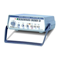
Identifies and explains front panel components and their functions.
Details rear panel connectors and power input options.
Covers first step setup, powering on, and basic output function/frequency setup.
Details on setting amplitude, DC offset, and duty cycle parameters.
Guides on configuring sweep, AM/FM modulation, and trigger functions.
Configuration for GATE/BURST, counter, VCF, GCV, TTL/SYNC outputs, and RS232.
Visual representation of internal components and MPU/power functions.
Details on VCF, waveform generation methods, and modulation principles.
Describes the operational principles of sweep, trigger, and frequency counter functions.