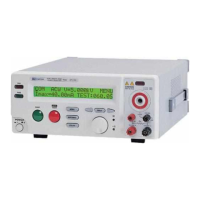
ELECTRICAL SAFETY TESTER
USER MANUAL
15
19 SOURCE+ Terminal
(only for Ground
Bond Test)
High current terminal for Ground Bond test.
20 Power Switch Press the power switch to turn on the tester.
21 SENSE+ Terminal Voltage Terminal for Ground Bond test.
22 SENSE- & Return
Terminal
SENSE- Terminal is a voltage terminal for
Ground Bond test, and Return Terminal is for all
test.
23 Ground Terminal Connect Ground terminal to the earth ground.
24 Fuse Holder with
Voltage Selector
To change AC source voltage,
ull the fuse holder
and rotate it to the proper value.
25 AC Inlet Connect the AC power line to the inlet.
26 Remote Interface The remote interface performs all the functions of
PLC control.
27 RS232 Terminal D-SUB 9 pin connector, Input/Output connector
for RS232.
28 GPIB Terminal Blue 24 connector, Input/Output connector for
IEE-488.
29 Scanner Interface D-sub 9 pins female connector for scanner box.
30
High Voltage Output
on rear panel
High voltage output terminal.
31
Sense + Terminal on
rear panel
Voltage terminal for Ground Bond test.
32
Source + Terminal
on rear panel
High current terminal for Ground Bond test.
33
Source - Terminal
on rear panel
High current terminal for Ground Bond test.
34
Sense - Terminal &
Return Terminal on
rear panel
Sense - terminal is a voltage terminal for Ground
Bond test, Return terminal is for all tests.
*The instrument can be used together with scanner box of HSB-001-1 &
HSB-001-2.
*The Instrument can control one scanner box only.
ELECTRICAL SAFETY TESTER
USER MANUAL
16
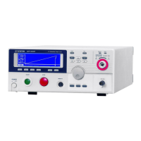
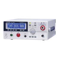
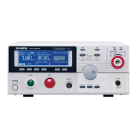
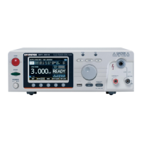
5. OPERATION METHOD
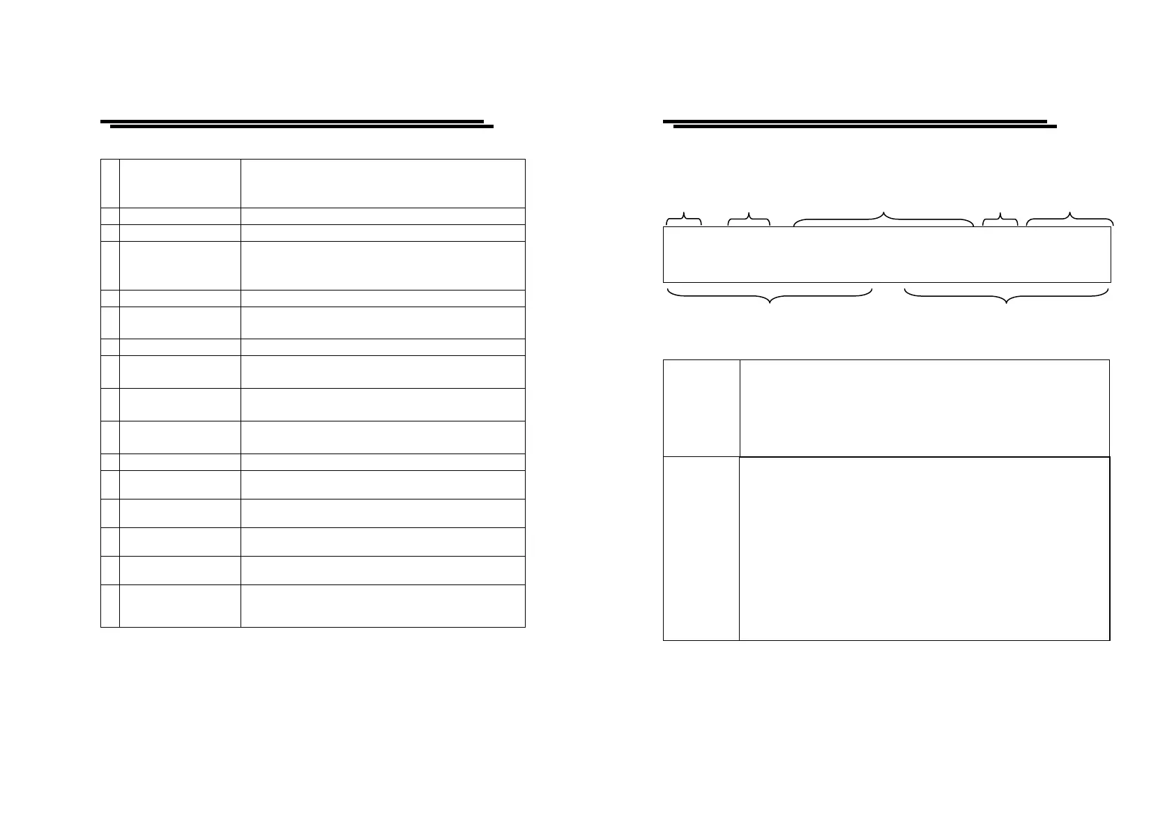
5-1. Main Display LCD
1 ~ 0 1 A C
WV=5
.000kV
*
R E A D Y
I
ax=0
1.00m
ATEST
:
000 . 0 s
Table of parameters
Storage
Group/ Step: There are total 10 groups, and each group has 16
steps.
The first number represents group while the second number
represents step.
Ex. 3:01
3 stands for group number, 01 stands for step number.
The test mode of tester includes:
ACW: AC Withstanding voltage test.
DCW: DC Withstanding voltage test (only for GPT-715A/
GPI-735A/745A).
I R : Insulation Resistance test (only for GPI-725A/GPI-735A
/745A).
G B : Ground Bond test (only for GPI-745A).
C N T : Continuity Check test (only for GPT-705A/715A/
GPI-725A/735A)
Mode
The total types of mode will change for different model.
Storage Mode Output Voltage/Current ARC Status
Measurement Limit Ramp/Test Time
 Loading...