PT-17
CONTENTS
OF
KIT(PARTS
LIST)
01.
PT17
Fuselage(Left
Side)
02. PT17 (Right Side)
03.
PT17MainWing(Up)
04. PT17 Main Wing(Down)
05.
PT17
Horizontal
Stabilizer
06.
PT17
Radial
Engine
07. Ultra-light Wheel Rlm(2")
08. Ultra-light
Wheel
Rlm(1")
09. Main Landing Gear(is(r2.0mm)
10. Tail Dragger(is)r1.2mm)
11.
Push
Rod Tube(is!r3.0x460mm)
12.
Plastic
Tube
is)r2.5x25mm
13.
Rubber
Grommet
Xl
XI
XI
xl
xl
xl
x2
xl
xl
xl
x2
x2
x2
01.
PTi7iim'(L)
xl
02.
PT17SliM(R)
xl
03.
PT17±M(Jl)
xl
04.
PT17iK(T)
xl
05.
PT17
7j(ipMH
xl
06.
PT17g|Ssi(D
xl
07.
ffl^Pftli(2")
x2
08.
®^3iftli(1")
xl
09. ±lilg('s?r2.0mm) xl
10. llli?!?(S(r1.2mm) xl
11.ffitfS^((?r3.0x460mm) x2
12.
Hggg
(is)
r2.5x25mm) x2
13.
hUMjIIMtIPS
x2
14.
Fiberglass
stick
xl
15. Aileron Linkage Wlre(L) xl
16. Aileron Linkage Wlre(R) xl
17. Elevator Linkage Wire
xl
18.
Push
Rod(is;r1mm) x3
19.
Plastic
Parts
Frame"A"
xl
20.
Plastic
Parts
Frame"C"
xl
21. Clay
xl
22.
Rubber
Gronnmet(is)5x3mm)
xl
23 Bolt(3x40mm) xl
24. Washer(3.2x8x0.5) xl
25. Nut(M3) xl
26. Cowling Fixing Screw(M1.4x9mm x20
— m m —
14.
15.
16.
17.
18.
19.
20.
21.
22.
23.
24.
25.
26.
iy*^i)tf(L)
H!JHiSfi]tT(R)
JiE^T(is)rlmm)
"A"
"C"
iBaa±
(<s(5x3mm)
MB
(3x30mm)
(3.2x8x0.5)
3ili
(M3)
(Ml .4x9mm TPA)
xl
xl
xl
xl
x3
xl
xl
xl
xl
xl
xl
xl
x20
27.
Electric
Power
System
EPS-350C
or
EPS-400C
xl
28.
Eps
Mount (10x10x90mm) xl
29. Propeller
(EP9070,
EP8060)
or(EP1060)
xl
30. Double-Side
Sponge
Tape
x4
31.GWSGIue
xl
32
Rubber
Band
x12
33.
Instruction
Manual
xl
34.
PT17Decal
xl
35.
GWS
Decal
xl
27.
28.
29.
30.
31.
32.
33.
34.
35.
S]t}M
EPS-350C
^
EPS-400C
S}ti^
(10x10x90mm)
(EP9070,
EP8060)
it
(EP1060)
mmm
GWS
SfflPTK
PT17l!^0Jl
PT17Bfiffi
GWS
xl
xl
xl
x4
xl
x12
xl
xl
xl
FUSELAGE
ASSEMBLY
at
03
$1
^
.
, 260
mm
,
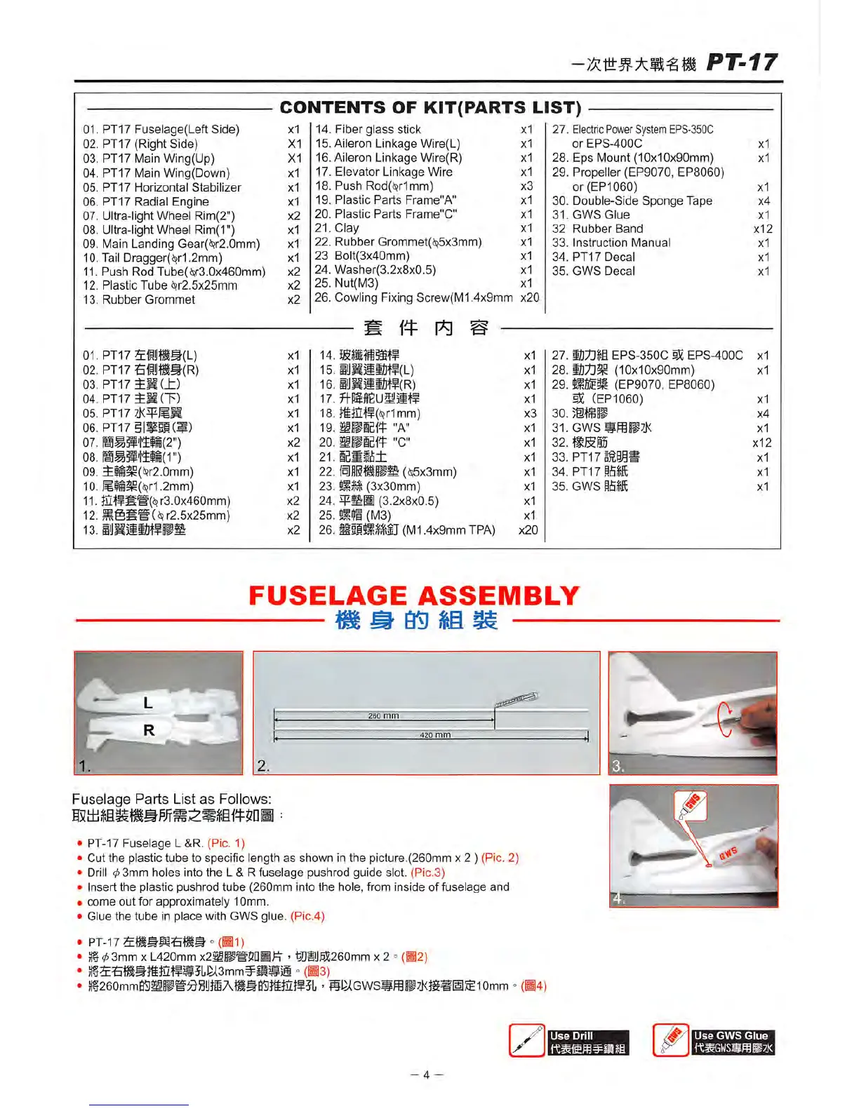
Fuselage
Parts
List
as
Follows:
PT-17
Fuselage
L&R.
(Pic. 1)
Cut
the
plastic
tube
to
specific
length
as
shown
in
the
picture.(260mm
x 2 ) (Pic. 2)
Drill 0
3mm
holes
into
the
L&R
fuselage
pushrod
guide
slot. (Pic.3)
Insert
the
plastic
pushrod
tube
(260mm
into
the
hole,
from
inside
of
fuselage
and
come
out
for
approximately
10mm.
Glue
the
tube
in
place
with
GWS
glue. (Pic.4)
• PT-17
»(Bl)
• jt§03mm XL420mm
x2ffiiig5DBt^
- ®iiJfiS260mm x 2 °
(^2)
• =
(B3)
•
}|f26Omm05fflBgfdSyffiA®9ffi)tiEff5L
-
BLMGWS«fflP7i<}g^
flillSlOmm °
(B4)
Use
Drill
- 4 -
Use
GWS
Glue
 Loading...