PT-17
r!'ra.-a933Bs-
.
7^
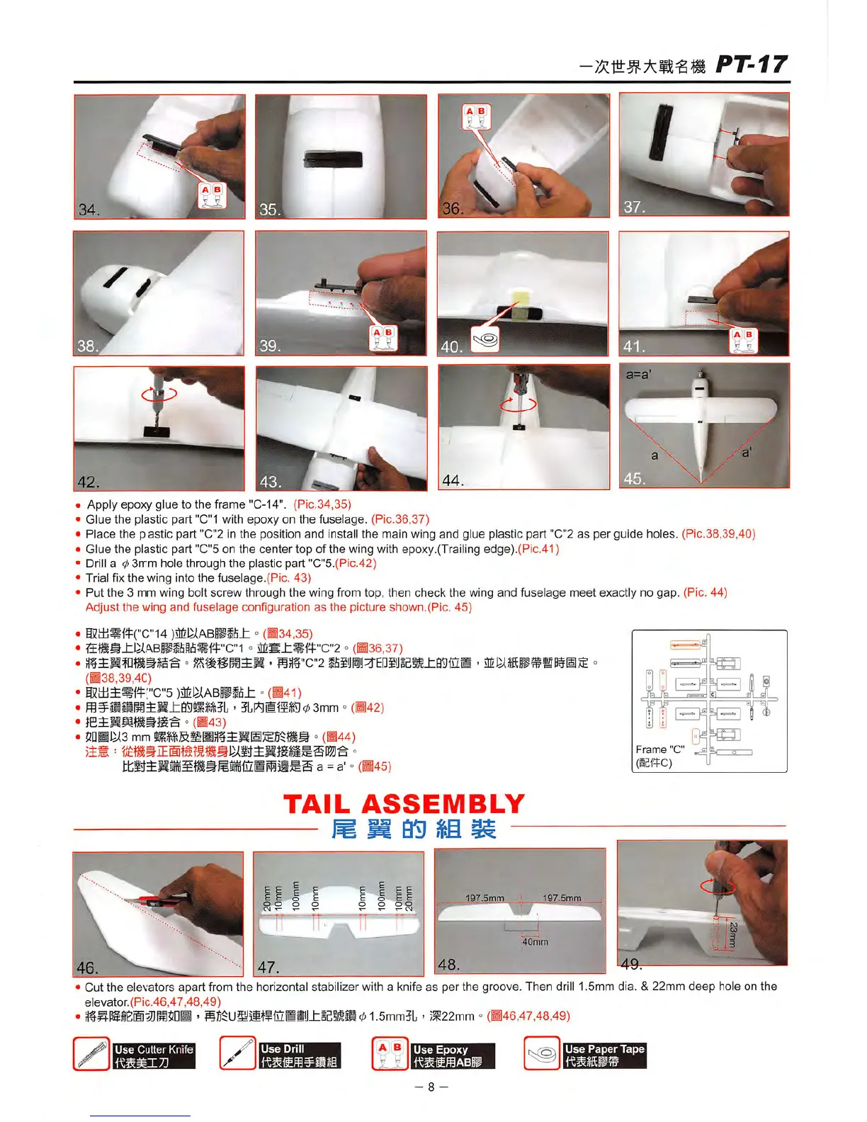
Apply epoxy glue to
the
frame "C-14". (Pic.34,35)
Glue
the
plastic
part
"C"1 with
epoxy
on
the
fuselage.
(Pic.36,37)
Place
the plastic part "G"2 in
the
position
and
install
the
main wing
and
glue plastic part "C"2
as
per
guide
holes. (Pic.38,39,40)
Glue
the
plastic part "G"5 on
the
center
top of the wing with epoxy.(Trailing edge).(Pic.41)
Drill
a
(p
3mm
hole through
the
plastic part "G"5.(Pic.42)
Trial fix
the
wing into
the
fuselage.(Pic.
43)
Put
the
3 mm wing bolt
screw
through
the
wing from top,
then
check
the
wing
and
fuselage
meet
exactly no
gap.
(Pic.
44)
Adjust
the
wing
and
fuselage
configuration
as
the
picture
shown.(Pic.
45)
®lli*ff("G"14
)mkkBmhh
" (•34,35)
Sffi»Jlli^ABPSfi|i5«ff"G"1
<=
aiigJl*ji|:"G"2
° (•36,37)
° -
s)if"G"2
ifiiijiij^EPsijiesiiffijua
(•38,39,40)
I5lifi5ff("G"5
"
(^41)
'
3Ll^ilfel5g03mm
-
(B42)
0
(143)
$nBI^3
mm
jLlMfiffiaHf
"
(B44)
a = a' o
(B45)
TAIL
ASSEMBLY
Q!)
m
40mm
Frame
C
(IBffC)
Gut the elevators
apart
from the horizontal stabilizer with a knife
as
per the groove. Then drill 1.5mm dia. &22mm
deep
hole on the
elevator.(Pic.46,47,48,49)
'
SB$Ugy5itf1uSB±ie5^S01.5mm5L
-
;3^22mm
=(•46,47,48,49)
Use
Cutter
Knife
Use
Drill
A B
Use
Epoxy
Use
Paper
Tape
- 8 -
 Loading...