80 CHAPTER 3: MULTIFUNCTIONAL INTERFACE MODULES
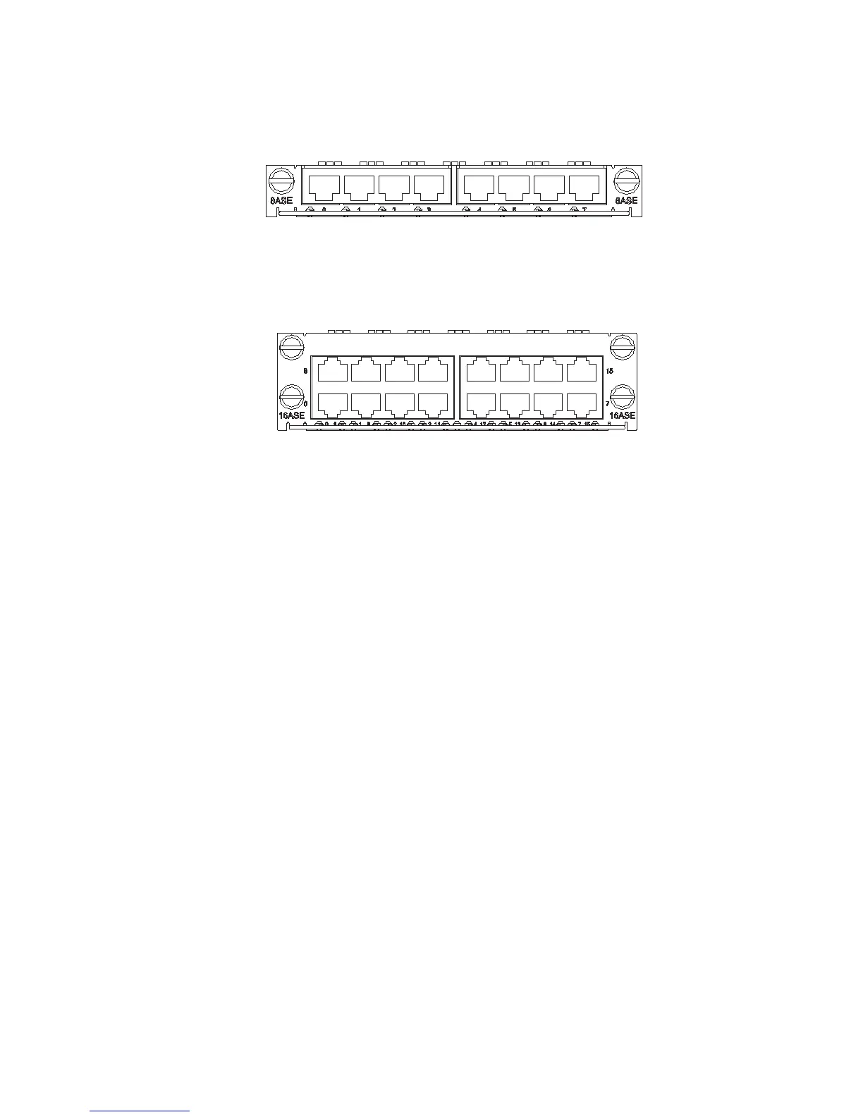
Figure 86 MIM-8ASE panel
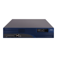
MIM-16ASE panel is shown in the following figure:
Figure 87 MIM-16ASE panel
Each channel on MIM-8ASE/MIM-16ASE has only one LED. It is ON when the link
is connected, and blinks when the link is active (that is, transmitting/receiving
data).
Interface Cable There are two types of interface cables for MIM-8ASE and MIM-16ASE: AUX cable
and dumb terminal cable (RJ-45-RJ-45), which can be made on site using a
network cable. See Low-End and Mid-Range Series Routers Cable Manual for their
pinouts.
c
CAUTION: AUX cable is optional. When ordering an MIM-8ASE or MIM-16ASE
module, please order an AUX cable also. By default, it is not provided. As for
dumb terminal cables, you can make them on site by reference to Low-End and
Mid-Range Series Routers Cable Manual.
Connecting the Interface
Cable
w
WARNING: Before plugging or unplugging interface cables connected to an
MIM-8ASE or MIM-16ASE module, power off the Router. Online insertion or
removal tends to damage the module and even the device.
c
CAUTION: Read the mark identifying a port before you connect a cable to it,
making sure it is the correct port. Wrong connection tends to damage interface
modules and even the Router.
Step 1: Check port type of the device to be connected and choose the correct
cable;
Step 2: Connect one end of the cable to the Router and the other end to the peer
device;
■ AUX cable
Connect the DB-25/DB-9 connector to the network device, usually a modem;