2-15
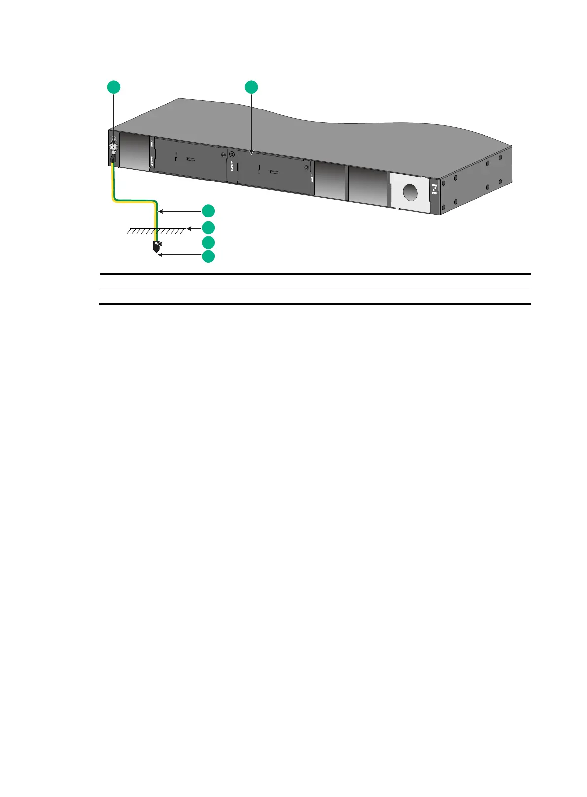
Figure2-20 Grounding the switch by burying the grounding conductor into the earth ground
Verifying the connection after grounding the switch
If you ground the switch by using a grounding strip, perform the following tasks:
a. Use a multimeter to measure the resistance between the switch grounding terminal and
grounding point, and make sure the resistance is less than 0.1Ω.
b. Use a grounding resistance tester to measure the grounding resistance of the grounding
strip, and make sure the grounding resistance is less than 1Ω.
If you ground the switch by using a grounding conductor buried in the earth ground, perform the
following tasks:
a. Use a multimeter to measure the resistance between the switch grounding terminal and
grounding point, and make sure the resistance is less than 0.1Ω.
b. Use a grounding resistance tester to measure the grounding resistance of the angle iron in
the ground, and make sure the grounding resistance is less than 10Ω. For locations with
high soil resistivity, sprinkle some resistance reducer to reduce soil resistivity or replace soil
around the grounding strip with soil with lower resistance.
For information about resistance measurement, see H3C Network Devices Lightning Protection
Guide.

 Loading...