Do you have a question about the Hach 5500sc PO4 3-HR and is the answer not in the manual?
Details the functions of the analyzer's keypad buttons and navigation keys.
Explains the elements shown on the analyzer's measurement and status screens.
Explains the meaning of color indicators for service and measurement quality.
Describes how to display and monitor measurements using graphs for up to six channels.
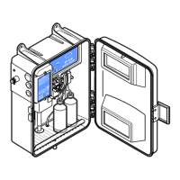
Identifies the location of the power switch, SD card slot, and indicator lights.
Step-by-step instructions for powering on the analyzer.
Guide for initial configuration settings after powering on the analyzer.
Details the options for analyzing specific samples or standards using the grab sample feature.
Procedure for measuring grab samples or standards using the grab sample funnel.
Method for manually dispensing a grab sample from a source for external analysis.
Configures the measurement cycle mode (interval or continuous).
Sets the time interval between measurements when in interval mode.
Selects the units for displaying measurement data.
Determines the number of measurements used for averaging.
Changes the name displayed for the analyzer.
Changes the name of the sample source displayed.
Activates or sets the measurement order for individual sample sources.
Configures the analyzer's action when no sample is detected.
Sets the analyzer's internal clock.
Adjusts display language, order, and contrast settings.
Stops scheduled maintenance alerts for specific analyzer components.
Displays software and serial number information for the analyzer.
Configures network card support for Modbus, Profibus, and HART.
Enables or disables the analyzer's passcode.
Manages the air purge function for external air supply.
Resets the analyzer configuration to factory defaults.
Shows the connected devices to the analyzer.
Removes a connected device from the analyzer's system.
Selects the sensor referring to variable X for calculations.
Selects the parameter referring to variable X for calculations.
Selects the sensor referring to variable Y for calculations.
Selects the parameter referring to variable Y for calculations.
Selects the calculation formula to be used for analysis.
Sets the number of decimal places for calculation results.
Enters the unit name for the measurement.
Enters the measurement name.
Configures the 4-20 mA output module settings.
Sets activation options for linear control, PID control, logarithmic, and bilinear functions.
Configures the analyzer's relay settings and functions.
Sets activation options for alarm, feeder control, event control, and scheduler functions.
Configures relay behavior based on low/high alarm values and deadbands.
Sets relay behavior for process value control based on setpoints.
Configures relay switching based on setpoints and timers.
Sets relay activation based on time schedules and days.
Sets warning levels for activation and individual warnings.
Configures relay closure during specific analyzer operations.
Holds outputs at the last value when communications are lost.
Transfers outputs to a pre-defined value when communications are lost.
Displays status information about the analyzer and its components.
Shows detailed measurement values and related parameters.
Accesses data logs and event logs for analysis.
Shows the analyzer's software information and serial number.
Displays connected modules with their software and serial numbers.
Starts grab sample operations for data exchange with laboratories.
Manages job files for laboratory data transfer or deletion.
Sets the minimum value for the job identification number.
Sets the maximum value for the job identification number.
Upgrades software on the SD card for specific devices.
Downloads and saves event and data logs from the analyzer.
Saves and restores analyzer settings and transfers them between instruments.
Reads device files or shows new measurement cycle scripts.
Initiates a manual calibration process for the analyzer.
Schedules automatic calibration routines for the analyzer.
Displays past calibration data and the next scheduled calibration date.
Manually enters calibration values, disabling automatic calibration.
Selects and sets 4-20 mA output values for calibration.
Resets calibration data and disables automatic calibration.
Configures the frequency and timing for automatic analyzer calibrations.
Guides the user through performing a manual calibration.
| Measurement Method | Colorimetric |
|---|---|
| Power Requirements | 100 - 240 VAC, 50/60 Hz |
| Enclosure Rating | IP66 |
| Light Source | LED |
| Detector | Silicon Photodiode |
| Operating Temperature | 5 to 45 °C |
| Output | 4-20 mA, RS-232 |
| Cycle Time | 3 minutes |
| Sample Volume | 5 mL |
| Power Supply | 100-240 VAC, 50/60 Hz |
| Accuracy | ±5% of reading or ±0.05 mg/L, whichever is greater |
| Sample Temperature | 5 to 50 °C |