Note: For illustration purposes, cable part number 08319=A=00xx is shown in Figure 4.
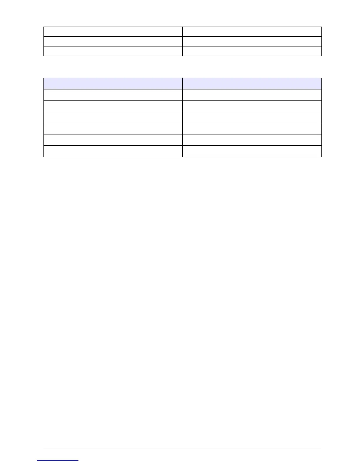
1 External shielding 4 External electrode
2 Internal shielding 5 Pt100
3 Internal electrode 6 Pt100
The cable is available in lengths of 5, 10 or 20 meters and must be connected in compliance with the
following table:
Function Color
External shielding White (red tip)
Internal shielding White (orange tip)
Internal electrode White (yellow tip)
External electrode Red
Pt100 Black
Pt100 Blue
Note: Refer to the user manual delivered with the transmitter for a detailed description of the cable connectors on
the transmitter.
Probe installation
In Figure 5 on page 8, Figure 6 on page 8 and Figure 7 on page 9 the annotations A, B and
C indicate:
• A: Ideal installation - perfect immersion of the electrode surfaces.
• B: Good installation - satisfactory immersion of the electrode surfaces.
• C: Poor installation - incomplete immersion of the electrodes, the conductivity will be too low.
On piping
Immerse the internal electrode completely in the process sample. For a 90° installation, take into
account the dimensions (see Dimensions on page 5).
Note: In the following illustrations, the arrows indicate the sample flow direction.
Installation example for the 8315 probe
English
7
 Loading...


